What engineers are most worried about at the industrial communication site? Communication interference! The CAN isolation module can effectively solve CAN bus communication interference problems and is easier to use than discrete device solutions. This article summarizes the details that CAN isolation module needs to pay attention to in use, to help you build a more reliable CAN bus network.
“Isolation†is the primary guarantee for the module to provide reliable data transmission for CAN node devices. Generally, the “isolation†of the isolation module means that after the module is powered on, it can provide signal isolation and power isolation for the node. The isolation voltage level is mainly 2500VDC and 3500VDC. . This article will start from the four levels of the front-end power protection, the rear-level grounding, the bus protection circuit and the actual networking of the CAN isolation module. The details of the use of the module will be introduced in all aspects to help you build a stable and reliable CAN bus network.
First, the front stage power protection
The primary interface of the module is facing the control signal. The power supply is usually the same as the CAN controller or MCU. In this case, it is recommended to add a 10μF filter capacitor to the power port. Some applications are the power supply of the module and the bus are transmitted together. For example, the power of each node of the 20 nodes is wired together with the CAN signal line, the node shares a power supply, or the module does not have a separate regulated power supply. This must be a module. The power supply adds TVS protection and filter capacitors, and ensures that the power supply is co-located with the signal, as shown in Figure 1 below.

Figure 1 power protection
Second, the rear stage is grounded
Generally, in the case of short distance and low interference, the CANG of the CAN transceiver can be suspended. However, in actual field applications, most of the CAN bus networks use shielded twisted pair cables. In this case, the shield layer needs to be grounded. If the grounding node is a metal casing and the primary system of the node is grounded, the shielding layer of the CAN port should be grounded through a 1000pF capacitor. The capacitor withstand voltage is greater than the module isolation withstand voltage. The circuit diagram is shown in Figure 2.

Figure 2 CAN port grounding diagram
Third, the bus protection circuit
The module CAN interface faces the bus and requires a higher level of surge and static protection. The CTM series module CAN interface bare metal can withstand ±4kV static and common mode ±2kV surge. Surge protection circuits can be added if a higher level is required. There are two kinds of protection circuits commonly used. The equivalent junction capacitance of the TVS tube in Figure 3 and Figure 4 is about 500~1000pF.

Figure 3 Bridge protection circuit

Figure 4 ordinary protection circuit
Figure 3 is a bridge circuit, characterized by small equivalent node capacitance, measuring capacitance between each line is less than 20pF, the circuit is suitable for occasions with a large number of CAN bus nodes and high communication speed.
The equivalent circuit capacitance of the common circuit shown in Fig. 4 is larger, and the capacitance between the lines is measured to be about 800 pF. This circuit is suitable for low-speed communication occasions.
Common-mode inductors: For common bus-mode interference and high EMI requirements, especially in the automotive industry, the 51μH common-mode inductor can effectively solve the problem. The problem with adding a common mode inductor is the introduction of resonant interference. When the bus signal rise and fall time of the transceiver is short, the common mode inductor resonates with the bus distributed capacitance, affecting communication. For example, in CAN FD applications, this resonance will affect the normal communication of the bus. Figure 5 shows the CTM5MFD module using ID segment 1Mbps, data segment 2Mbps rate communication, adding the waveform of the protection circuit, where green is the waveform of the common mode inductor and pink is the waveform without common mode inductor.
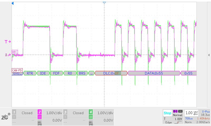
Figure 5 surge circuit added to the inductor waveform comparison
In addition to the effects of the bus distribution parameters, the CAN differential signal of the module itself also affects the resonant voltage amplitude. The CAN transceiver meets the following two conditions to help reduce the resonant voltage amplitude.
The CANH and CANL signals should be synchronized and have good symmetry;
The differential voltage signals formed by CANH and CANL have small rise and fall slopes.
Fourth, the actual network
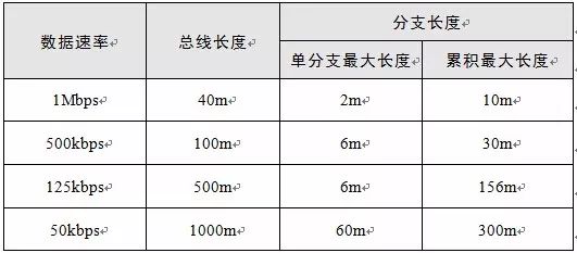
Most of the general CAN isolation modules have explicit timeout protection. The minimum baud rate of the module is limited to 40kbps, and the maximum communication distance when the module is networked should be 1km. When the maximum baud rate of bus communication is determined, the bus length and branch length of the networking shall not exceed the limit of Table 1.
Table 1 Network length under different baud rates
For common application networking, refer to the recommended networking mode that has been given in the CTM series isolated transceiver data sheet, that is, a single-layer shielded twisted pair cable. The reference networking method using double-layer shielded twisted pair is given below. This method is a three-wire transmission mode, and the transmission effect and anti-interference are the best. When the network is connected, the outer shield of the twisted pair is connected to the earth at a single point. The inner shield and the twisted pair are connected to CANG, CANH and CANL of each transceiver. The CANG of each CAN node is connected to the equipment casing through a 1000pF capacitor.
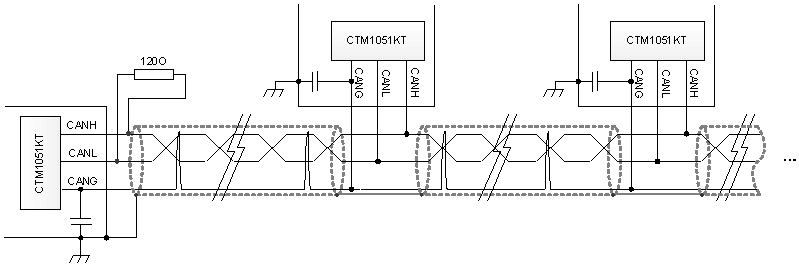
Figure 6 Schematic diagram of three-wire transmission networking
Copper Tube Terminals Without Checking Hole
Our company specializes in the production and sales of all kinds of terminals, copper terminals, nose wire ears, cold pressed terminals, copper joints, but also according to customer requirements for customization and production, our raw materials are produced and sold by ourselves, we have their own raw materials processing plant, high purity T2 copper, quality and quantity, come to me to order it!
Copper Tube Terminals Without Checking Hole,Cable Lugs Insulating Crimp Terminal,Cable Connector Tinned Copper Ring Terminal,Tubular Cable Lugs Crimp Terminal
Taixing Longyi Terminals Co.,Ltd. , https://www.lycopperterminals.com