The digital frequency meter designed this time is based on AT89C52. The software is programmed with C51 language. The measurement adopts multi-cycle synchronous measurement method, which avoids the lack of precision of direct measurement method and eliminates the combination of direct and indirect. The method needs to judge the inconvenience caused by the relationship between the frequency of the signal to be tested and the intermediate frequency, and can achieve high equal precision frequency and period measurement.
Hardware circuit designThe basic idea of ​​the multi-cycle synchronous measurement method is to synchronize the signal under test with the gate, thereby fundamentally eliminating the ±1 quantization error when counting the measured signal during the gate time, so that the measurement accuracy is greatly improved. The countdown counter is an instrument with an innovative idea of ​​frequency measurement and measurement cycle designed based on this method. It uses a multi-cycle synchronous measurement method, that is, measuring multiple (integer) period values, and then performing a reciprocal operation to obtain the frequency. The advantage is that the same high test accuracy and resolution can be achieved over the entire frequency range.
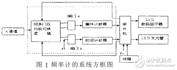
1. System level design
In the case of selecting an accuracy measurement method such as multi-cycle synchronization, a system-level block diagram of the frequency meter can be drawn according to a top-down design method, as shown in FIG. According to the principle of measurement cycle and frequency, the overall block diagram can be divided into three subsystems: input channel (ie, pre-shaping circuit). This part is mainly composed of analog circuits; multi-cycle synchronization and other precision frequency, period measurement, control and function Switching (middle part), this part is basically composed of digital hardware circuits; single chip and peripheral circuits, including single chip microcomputer, digital display.
2, subsystem design
1. Input channel design. The input channel is composed of a preamplifier and a shaper, so the gain and bandwidth specifications of the preamplifier are estimated. In order to accurately measure the signal, the input signal is passed through an amplification shaping circuit. The specific implementation scheme is as follows: the input signal is amplified by the LM358 operational amplifier, and then shaped by the 74LS132. At this time, the signal cannot be directly sent to the single-chip microcomputer, because the CPU cannot control the signals of the INT0 and INT1 pins in the hardware, and the solution is solved. This problem is solved by hardware and software.
2. Preset gate time generation circuit design. The gate time is determined by a 555 timer to generate a pulse signal, and the pulse signal generated by 555 is sent to the 74LS90 decimal counter. Since the 74LS90 has a binary-hexadecimal mixed count function, it can be used to implement The hexadecimal count connects the output of the 74LS90 to the input of the 3-8 line decoder 74LS138, and then connects the output end of the decoder to five LEDs, so that the gate time control on the hardware can be realized. However, considering the complexity of the hardware implementation, it can be realized by software. It is realized that the five LEDs are directly connected to the P1 port of the MCU, and the gate time is changed by the button.
3. Digital display circuit design. This part of the circuit is composed of a one-way eight-bit shift register 74LS164 and a digital tube. Taking into account the accuracy problem, take five-digit count value, use five 74LS164 cascade, and also display the frequency and period units, so you need to cascade another 74LS164, and connect six unit indicators on the output of 74LS164. Representing three different unit orders of magnitude for the periodic frequency, namely the period unit s, ms, μs and frequency units Hz, KHz and MHz. The clock signal of the shift register is controlled by the serial output port TXD of the microcontroller.
Aluminum substrate is a metal-based copper clad laminate with good heat dissipation function. Generally, a single-sided panel consists of three-layer structure, which are circuit layer (copper foil), insulating layer and metal base layer,and are usually used in products that require heat dissipation, such as solar energy,Led light etc.
Metal Core PCB,FR4 PCB Board,Double-sided Aluminum PCB,Single Sided Board,Aluminum Based Circuit Board
Huizhou Liandajin Electronic Co., Ltd , https://www.ldjpcb.com