In the industrial control, the MCS-51 series MCU is often used. In order to prevent the program from running, it is often connected to a watchdog circuit. The watchdog circuit can perform both power-on reset and freeze-reset functions. The price of finished watchdog ICs such as the MAX813L is generally higher. An inexpensive watchdog circuit consisting of a general purpose digital circuit CD4011 is now described.
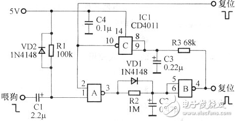
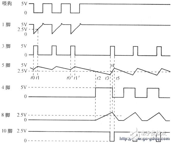
The figure above is a watchdog circuit consisting of a NAND gate CD4011, and Figure 2 is a pin waveform diagram. As can be seen from the above figure, the three NAND gates A, B, C are connected in series to form a loop without considering the dog feed signal of the 1 leg. Due to the action of the delay circuits of VD1, R2, C2, and R3, C3, they will form an oscillator. Normally, the 2nd pin of NAND gate A is high level (see the description of charging and discharging VDI, R2, C2 caused by feeding dog signal later), the dog feeding signal (high level to low level hopping) at 10 o'clock through R1 After C1 is differentiated, it is sent to pin 1. Its output 3 pin becomes high level, and C2 is charged by CDI, and C2 is quickly filled to 5V. The input terminals 5 and 6 of the NAND gate B are at a high level, and the output terminal 4 is at a low level. At the time t1 after the feeding pulse edge, the 1 pin returns to the high level, the 3 pin becomes the low level, and the low level discharges to the C2 through R2, and the discharging speed is much slower than the charging speed. When the C2 voltage drops from 5V to about 2.5V, the 4th pin of NAND gate B will change from low to high. In normal operation, before the 4 pin goes high, a new dog feed signal comes, and the 3 pin goes high again, and C2 quickly fills up to 5V. Therefore, pin 4 remains low, and pin 10 of NAND gate C remains high. Once the dog signal is lost, the 4 pin will go high at 12 o'clock after a delay (t2-t0'), which is the CPU reset.
The high level is also delayed by R3 and C3, so that the input terminals 8 and 9 of the NAND gate C become a high level at time t3, and the output terminal 10 becomes a low level. Then cause 2 feet to be low, 3 feet to be high, and C2 to charge quickly. At time 14 C2 voltage exceeds 2.5V, pins 5 and 6 become high, and pin 4 goes low. C3 discharge, after R3, C3 delay, at time t5, 8 feet become low level, 10 feet return to high level, 3 feet return to low level. Thus, when there is no dog feed signal, the 4 pin will output a positive pulse train reset signal with a period of 100 ms and a width of about 5 ms. The width of the reset signal is determined by R3 and C3. The period is determined by R2 and C2. The 10th pin of NAND gate C will output the negative pulse train reset signal. At the moment of power-on, since the initial voltages of C2 and C3 are both zero, pins 5, 6, 8, and 9 are low, and pin 4 is high for CPU reset. After about 5ms, 8 feet and 9 feet become high level, then 10 feet become low level, 3 feet are high level, C2 is quickly filled, 4 feet become low level, and 10 feet are delayed by R3 and C3. Return to high level and the power-on reset process ends. This circuit works well in a variety of MCS-51 series microcontrollers. In order to verify the reliability of the circuit, the IC1 pin can be short-circuited to ground when the power is on, that is, the dog feed signal is stopped, and the waveforms of the 4 and 10 pins are measured with an oscilloscope, and the reset signal as shown in the following figure can be seen. Waveform.
At present, the market price of CD4011 is about 0.6 yuan, lN4148 is 0.05 yuan, the capacitance is 0.04 yuan, and the resistance is 0.01 yuan. The cost of the watchdog circuit component is less than 0.9 yuan. The market price of the watchdog integrated circuit MAX813L is about 6 yuan, and the SP706S is about 5 yuan. Obviously the cost of this circuit is much lower than that of a single-chip watchdog IC. The CD4011's extra NAND gate can also be used as it.
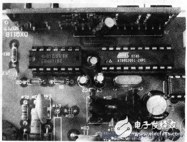
The picture above is the real thing of a TV tuner. The TV tuner has a switching power supply, a radio frequency amplifier, a frequency synthesis integrated TV tuner, and a control circuit. The CPU of the control circuit selects AT89C2O5l, memory AT24CO2, and signal detection uses LM567. The watchdog circuit uses the circuit consisting of the CD4011 described earlier.
Screw Terminal Block,Screw Terminal,Screw Terminal Connector,Pcb Screw Terminal
Cixi Zhongyi Electronics Factory , https://www.zybreadboard.com