The analog LED dimming design is simple and low cost, but it is not suitable for applications requiring stable color temperature; digital PWM dimming color temperature control is better, but it must be matched with MCU to increase system cost. Designers should consider the application requirements and choose the most suitable dimming solution to achieve the desired LED lighting color and brightness.
Color accuracy is important in lighting applications such as buildings, areas and xenon lamps, and light-emitting diodes (LEDs) are ideal for providing accurate color. LED color can vary with colors such as red, blue, green, yellow, and white; when multiple colors are mixed, the brightness must be adjusted. This article introduces the dimming techniques of various LED color mixing.
Accurate channel brightness control LED for rich color
Each LED crystal can only emit monochromatic light. If you want to create other colors, you can use the red, green and blue LED lights to mix, as long as you switch the red, green and blue LED channels, you can produce seven basic colors (red, Green, blue, yellow, purple, light green, white).
If you need more rich colors, you only need to control the brightness of the LED lights of the three primary colors to produce a variety of colors, including adjusting the brightness of each LED channel, and controlling the current control through the LED strings. When changing the color temperature of the LED white light, the red and white LED strings are usually adjusted.
There are two basic ways to adjust LED brightness: Analog and Pulse Width Modulation (PWM). Both control the average current through the LED string by installing a switch mode or a linear LED driver to change the brightness of the LED.
Figure 1 shows a dual-string LED driver that includes a buck switch and a linear regulator. Both LED strings can be selected analog or PWM, both of which have advantages and disadvantages. Most applications are based on the choice of color mixing performance.
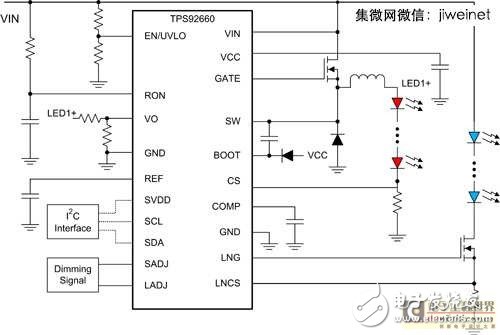
Figure 1. A dual string dimmable LED driver with a buck converter and a linear regulator.
Analog dimming must master the magnitude of current change
LED analog dimming is to control the LED current reference voltage in the chip by controlling the constant current through the LED string, or to control the LED current sensing voltage outside the chip.
Most LED drivers, including switching regulators and linear regulators, the LED current is determined by Equation 1:
![]() . . . . . . . Formula 1
. . . . . . . Formula 1
VREF is the LED current reference voltage in the chip, and RSNS is the voltage sensing resistor.
The LED current can be adjusted by changing VREF. Some LED driver chips do not allow the user to change the LED current reference voltage. In a wafer that allows changing the LED current reference, there are usually two ways to change it: one is to add an analog voltage to the reference voltage adjustment pin provided by the chip; To adjust the reference voltage through the digital communication interface such as I2C, as shown in Figure 1, the LED current reference voltage can be adjusted by the I2C command.
Another type of dimming method is to change the LED current sensing voltage. The current sense resistor of most applications is less than 1 ohm, so there is no need to use a potentiometer to change the current sense resistor, which can be achieved by adding an external DC voltage to the current sense pin of the chip. effect. Figure 2 shows the change of the current sensing voltage. The typical analog dimming line, the voltage of the CS pin can refer to the following formula 2:
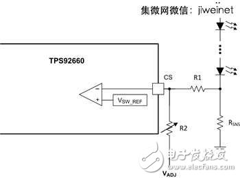
Figure 2 Analogy dimming line example
![]() . . . . . . Formula 2
. . . . . . Formula 2
In a stable state, the CS pin voltage will be equal to the reference voltage. The LED current can be changed by adjusting the external DC voltage or by adjusting the value of the variable resistor R2.
The use of analog dimming in color mixing applications will find a disadvantage. Because the LED color temperature will vary with current, if the analog dimming current changes a lot, the LED brightness and color may also change, resulting in the inability to produce the desired color.
PWM dimming color temperature control precision
PWM dimming is determined by a fixed cycle period and a frequency switch LED. For the dimming LED current calculation, refer to the following formula 3:
![]() . . . . . . . Formula 3
. . . . . . . Formula 3
IDIM is the dimmed LED current, D is the periodic cycle of the PWM dimming signal, and ILED is the dimming-free LED current.
The LED PWM dimming frequency is usually higher than 200Hz and is invisible to the naked eye. Many LED driver chips have PWM dimming input pins that receive PWM dimming input signals from a microcontroller (MCU). Usually, only when the PWM dimming signal becomes weak, the driver chip turns off the MOSFET driver; when the signal is strong, the MOSFET driver turns on again; in addition, the internal line is turned off when the PWM dimming cycle is turned off. It continues to operate, avoiding the need for the chip to restart, causing a delay in the PWM dimming edge.
In switch-mode LED drivers, the capacitor is usually placed in the LED string, filtering high-frequency switching noise, and slowing the rising edge of the PWM dimming LED current. Therefore, high frequency, low cycle PWM dimming applications must remove the capacitor. Figure 3 shows the PWM dimming waveform of the LED buck regulator with no output capacitor.

Figure 3 PWM dimming LED current waveform
Analog to PWM dimming with overheat protection
Some LED driver chips have an analog-to-PWM dimming function. After the chip dimming pin receives the analog signal, it is converted into a PWM dimming signal. The PWM dimming frequency is fixed and the cycle period is proportional to the input analog signal level.
If there is no MCU in the lighting application, the analog to PWM dimming scheme will greatly benefit. Analog to PWM dimming design can play the role of overheat protection. If the temperature of the LED board exceeds the set value, PWM dimming can reduce the LED current.
Shunt FET PWM dimming for high frequencies
Shunt FET PWM dimming is typically used for very high frequency LED PWM dimming. Figure 4 shows a shunt FET PWM dimming circuit based on a buck regulator. The external shunt FET is placed parallel to the LED string to quickly bypass the converter output current. When the shunt FET is turned on, the LED string is turned off, and vice versa. Of course. Therefore, the LED string passes through the shunt FET to achieve effective PWM dimming. Some LED driver chips provide MOSFET drivers for shunt FET PWM dimming, so no external MOSFET drivers are required.

Figure 4 Example of shunt FET PWM dimming
During the shunt FET PWM dimming process, the inductor current of the switching regulator remains the same, and the inductor current rises and falls without causing a delay. With a powerful MOSFET driver, the shunt FET can be switched at very high speeds, so the PWM dimming LED current ramp is quite sharp. Shunt FET PWM dimming is ideal for high frequency PWM dimming applications.
Ideal LED lighting depends on multiple considerations
In LED color mixing applications, dimming is important to achieve the desired color and brightness. LED dimming methods are numerous, mainly analog dimming and PWM dimming. The analog dimming circuit is simpler and lower in cost, and is also suitable for systems without MCU, but it is not suitable for applications requiring stable color temperature. On the other hand, PWM dimming can reduce the chromatic aberration caused by LED current variation, so it can reach quite Accurate color temperature, but PWM dimming generally requires the microprocessor to generate input digital signals, thus increasing system cost.
Tianma Microelectronics Co.,Ltd., founded in 1983, is a high-tech enterprise specializing in the production and operation of liquid crystal display (LCD) and liquid crystal display module (LCM). After more than 30 years of development, has developed into a set of LCD research and development, design, production, sales and service as one of the large public listed companies. Tianma of Shenzhen, Tianma of Shanghai, Tianma of Chengdu, Tianma of Wuhan, Tianma of Xiamen, Tianma of Europe, Tianma of the United States, Tianma of South Korea, etc. STN-LCD, CSTN-LCD, TFT-LCD and CF production lines and module factories. The company's marketing network throughout the world, products are widely used in mobile phones, MP3/MP4, on-board display, instrumentation, household appliances and other fields. In terms of technical level, product quality, product grade and market share, it ranks among the top in the same industry in China and has become a leading enterprise in the field of small and medium-sized display.
The company is mainly engaged in the design, manufacture and sales of LCD and related materials, equipment and products, providing related technology development, technical consultation, technical services and technology transfer, and engaged in the import and export of goods and technology. Specializing in LCD screen and module design, research and development, manufacturing, sales and after-sales service. Production used for LCD, laptop, LCD TV, digital video and audio, car GPS, industrial medical products and other models of display screen and module. Products are widely used in mobile terminals, car display, aviation display, industrial control medical, entertainment display and other small and medium-sized display fields.
Tianma TFT-LCD,Nextion 3.5,Arduino Tft Screen,Raspberry Pi 3.5 Lcd,3.5 Inch Raspberry Pi Screen
TONYA DISPLAY LIMITED , https://www.tydisplay.com