Based on the classical electromagnetic theory, people convert the physical quantities such as displacement, position, liquid level, size, flow rate, speed and vibration that are not convenient for quantitative detection and processing into electrical quantities that are easy to quantitatively detect and convenient for information transmission and processing. This is the displacement sensor that is widely used in production and life.
Motion detector
Displacement sensor, also known as linear sensor, is a linear device belonging to metal induction. The function of the sensor is to convert various measured physical quantities into electricity. The displacement is the amount related to the movement of the position of the object during the movement, and the range of measurement of the displacement is quite extensive. Small displacements are usually detected by strain gauge, inductive, differential transformer, eddy current, and Hall Sensors. Large displacements are commonly measured by sensing technologies such as inductosyn, grating, capacitive grid, and magnetic grid. Among them, the grating sensor has the advantages of easy digitization, high precision (currently the highest resolution can reach nanometer level), strong anti-interference ability, no human error, easy installation, reliable use, etc., in machine Tool processing, instrumentation and other industries. Get an increasingly wide range of applications.
Classification and principle of displacement sensors
According to the working principle:Potentiometer displacement sensor
It converts the mechanical displacement into a resistive or voltage output that is linear or arbitrary as a function of the potentiometer element. Both the ordinary linear potentiometer and the circular potentiometer can be used as linear displacement and angular displacement sensors, respectively.
However, a potentiometer designed to achieve the purpose of measuring displacement requires a certain relationship between the change in displacement and the change in resistance. The movable brush of the potentiometer type displacement sensor is connected to the object to be measured.
The displacement of the object causes a change in the resistance of the mobile end of the potentiometer. The amount of change in resistance reflects the magnitude of the displacement, and the increase or decrease in the resistance indicates the direction of the displacement. A power supply voltage is typically applied to the potentiometer to convert the change in resistance to a voltage output. The wirewound potentiometer changes its resistance with a åŒ resistance as a step when its brush moves, and its output characteristics are also stepped. If such a displacement sensor is used as a displacement feedback element in a servo system, an excessive step voltage will cause the system to oscillate. Therefore, the resistance value of each turn should be minimized in the fabrication of the potentiometer. Another major drawback of potentiometer sensors is their tendency to wear. Its advantages are: simple structure, large output signal, convenient use and low price.
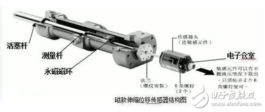
Magnetostrictive displacement sensor
The magnetostrictive displacement sensor measures the actual displacement value of the detected product by accurately detecting the absolute position of the movable magnetic ring by internal non-contact measurement and control technology.
The magnetostrictive principle is used to accurately measure the position by generating a strain pulse signal by intersecting two different magnetic fields. The measuring element is a waveguide, and the sensitive elements in the waveguide are made of a special magnetostrictive material. The measurement process is to generate a current pulse from the sensor's electronics chamber that is transmitted within the waveguide to create a circumferential magnetic field outside the waveguide that intersects the magnetic field generated by the moving magnetic ring that is placed over the waveguide as a positional change. At the time of the magnetostriction, a strain mechanical wave pulse signal is generated in the waveguide, and the strained mechanical wave pulse signal is transmitted at a fixed sound speed and is quickly detected by the electronic chamber.
The transmission time of the strained mechanical wave pulse signal in the waveguide is proportional to the distance between the movable magnetic ring and the electron chamber, and by measuring the time, the distance can be determined with high accuracy. Since the output signal is a true absolute value, rather than a proportional or amplified signal, there is no signal drift or variable value, and there is no need to periodically re-mark.
The magnetostrictive displacement sensor is a high-precision, long-stroke absolute position measurement displacement sensor manufactured according to the principle of magnetostriction. It adopts the internal non-contact measurement method. Since the movable magnetic ring for measurement and the sensor itself are not in direct contact and are not rubbed or worn, they have long service life, strong environmental adaptability, high reliability and good safety. It is easy to automate the system and work normally even in harsh industrial environments (such as oily, dusty or other contaminated areas). The sensor uses high-tech materials and advanced electronic processing technology, so it can be used in high temperature, high pressure and high oscillation environment. The sensor output signal is an absolute displacement value. Even if the power is interrupted or reconnected, the data will not be lost, and there is no need to reset to zero. Since the sensitive components are non-contact, even if the detection is repeated, no damage will be caused to the sensor, which can greatly improve the reliability and service life of the detection. The stroke can be up to 3 meters or longer, the nominal accuracy is 0.05% F·S, the accuracy of the sensor above 1 meter is 0.02% FS, and the repeatability is up to 0.002% F·S, so it is widely used.
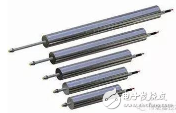
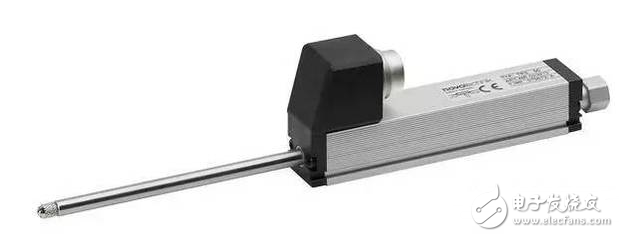
Linear displacement sensor
The function of the linear displacement sensor is to convert the linear mechanical displacement into an electrical signal. In order to achieve this effect, the variable resistance rail is usually fixed at the fixed part of the sensor, and different resistance values ​​are measured by the displacement of the slider on the slide rail. The sensor rail is connected to a steady-state DC voltage that allows a small current to flow through the microamperes, and the voltage between the slider and the start is proportional to the length of the slider movement. Using the sensor as a voltage divider minimizes the accuracy of the total resistance of the rail, as changes in resistance caused by temperature changes do not affect the measurement.
Angular displacement sensor
Angle Displacement Sensors are used in obstacle handling: using angle sensors to control your wheels can indirectly detect obstacles. The principle is very simple: if the motor angle sensor is configured to run and the gear does not turn, your machine has been blocked by obstacles. This technique is very simple to use and very effective; the only requirement is that the moving wheels cannot slip on the floor (or too many times), otherwise you will not be able to detect obstacles. This problem can be avoided by connecting an idling gear to the motor. This wheel is not driven by the motor but is driven by the movement of the device: if the idler stops during the rotation of the drive wheel, you are experiencing obstacles. .
According to the test materialHall-type displacement sensor
Its measuring principle is to keep the excitation current of the Hall element (see the semiconductor magneto-sensitive element) constant and move it in a gradient-normal magnetic field, and the displacement is proportional to the Hall potential of the output. The larger the magnetic field gradient, the higher the sensitivity; the more uniform the gradient changes, the closer the relationship between the Hall potential and the displacement is linear. In Fig. 2, there are three kinds of magnetic systems that generate gradient magnetic fields: a system has a narrow linear range, and when the displacement Z=0, the Hall potential is ≠0; b system has good linearity when Z “2 mm, Z=0, Hall potential = 0; c system sensitivity is high, the measurement range is less than 1 mm. In the figure, N and S respectively indicate positive and negative magnetic poles. The Hall-type displacement sensor has a small inertia, high frequency response, reliable operation, and long life. Therefore, it is often used to convert various non-electric quantities into displacements and then perform measurement.
Photoelectric displacement sensor
It measures the displacement or geometry of an object based on how much light is blocked by the object being measured. It is characterized by non-contact measurement and continuous measurement. Photoelectric displacement sensors are commonly used to continuously measure wire diameter or as edge position sensors in strip edge position control systems.
Cable Clamper,Emc Shielded Cable Clamp,Din Rails Clamper,Shield Cable Clamp
Kunshan SVL Electric Co.,Ltd , https://www.svlelectric.com