The Butterworth filter is characterized by a maximum flat frequency response curve in the passband, no ups and downs, and a gradual drop to zero in the blocking band. On the Bode plot of the logarithmic diagonal frequency of the amplitude, starting from a certain corner frequency, the amplitude gradually decreases with the increase of the angular frequency, and tends to be negative infinity.
The first-order Butterworth filter has a decay rate of 6 dB per octave and 20 dB per decade. The attenuation rate of the second-order Butterworth filter is 12 dB per octave, the attenuation rate of the third-order Butterworth filter is 18 dB per octave, and so on. The amplitude of the Butterworth filter monotonically decreases, and is the only filter that maintains the same shape regardless of the order, amplitude and angular frequency curves. Only the higher the filter order, the faster the amplitude attenuation in the blocking band. The higher-order amplitude diagonal frequency maps of other filters and the amplitude-to-angular frequencies of lower-order numbers have different shapes.
Design stepsFor example, to design a digital low-pass filter, the technical specifications are:
Passband critical frequency fp, attenuation in the passband is less than rp;
The stopband critical frequency fs, the attenuation within the stopband is greater than αs; the sampling frequency is FS
1. Change the index to an angular frequency wp=fp*2*pi; ws= fs*2*pi;
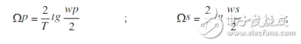
2. Convert the frequency index {Wk} of the digital filter from wk=(2/T)tan(Wk/2) to the frequency index {wk} of the analog filter. Since it is designed by the bilinear invariant method, Take predistortion.
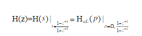
3. Convert Qualcomm indicators into low-pass indicators, and then design Qualcomm's s-domain model
4, normalized processing
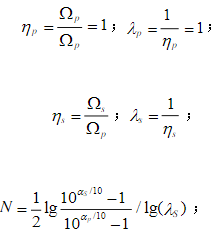
Calculate N from the above three formulas, and look up the table to obtain the order of the analog low-pass filter, so that the parameters of the analog high-pass filter are determined by the following equation.
Its program is:
Fp = 400 fs= 300;
Rp = 1; Rs = 20;
Wp =fp*2*pi;
Ws =fs*2*pi;
FS=1000; T=1/FS;
The program execution result is: wp=2.5133e+003 ws=1.8850e+003 Comply with the actual calculation result.
Digital domain frequency for predistortionIts program is:
Wp2=2*tan(Wp/2)/T;
Ws2=2*tan(Ws/2)/T;
After predistortion, the frequency can be found to be: wp2= 6.1554e+003
Ws2= 2.7528e+003
Analog filter designIts program is
% design analog filter
[N,Wn] = buttord(wp2,ws2,Rp,Rs,'s')
Wuhan University of Technology "Digital Signal Processing" report
9
[z,p,k]=buttap(N); %Create a Buttord low-pass filter prototype
[Bap, Aap]=zp2tf(z,p,k); % is converted from a pole to a transfer function
Figure(1) freqs(Bap,Aap); % analog low-pass filter frequency response
TItle ('frequency response of analog filter (low pass prototype)')
[Bbs, Abs] = lp2hp (Bap, Aap, Wn); % analog low pass Qualcomm
Figure(2)
Freqs(Bbs,Abs);
TItle ('frequency response of analog filter')
After the program is executed, the frequency response can be found as: N=4, and its waveform is as shown below.
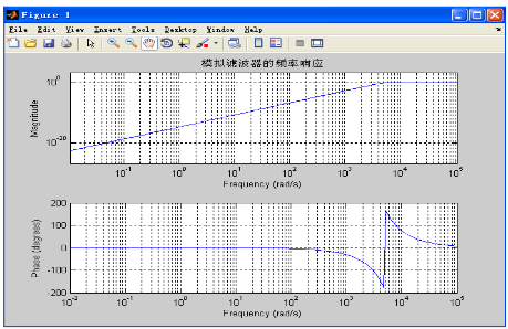
Analog filter frequency response
It can be obtained from the above analysis: it conforms to the general characteristics of Qualcomm and has the same effect as expected. Under this condition, the waveform of the Butterworth filter low-pass prototype is shown below.
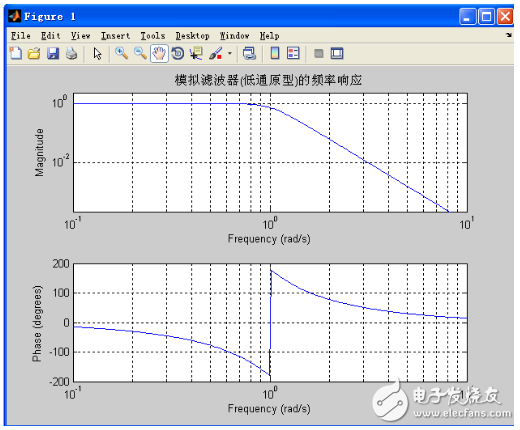
Frequency response of analog filter (low pass prototype)
In the design process, a problem involving frequency conversion, that is, the simulation of low-pass prototypes into high-pass, its functions and usage are as follows:
[b,a]=lp2hp(Bap,Aap,Wn);
Function: Convert the analog filter prototype into a high-pass filter with a cutoff frequency of Wn. Where Bap and Aap are respectively the molecular vector and the denominator vector of the low-pass transfer function;
b, a are the numerator vector and the denominator vector of the high-pass transfer function, respectively.
Analog filter becomes digital filterIts program is:
[Bbz, Abz] = bilinear (Bbs, Abs, FS); % Design the digital filter freqz (Bbz, Abz, 512, FS) by bilinear transformation;
The result of running the program is as follows:
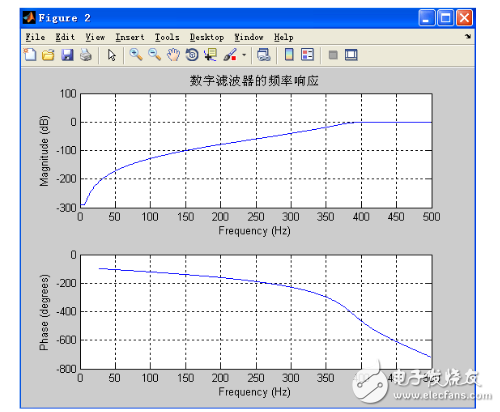
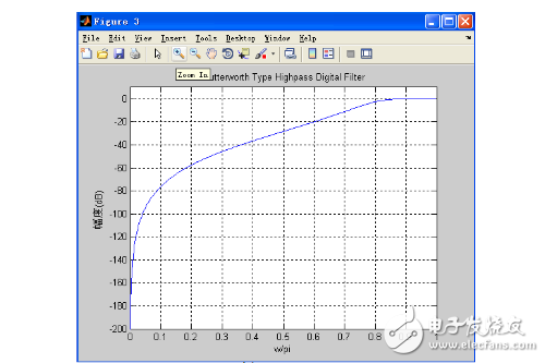
Digital filter frequency response
Due to the bilinear invariant method, the phase is nonlinear. The main reason here is to obtain a detailed frequency response by obtaining a strict frequency response and controlling the position of the cutoff frequency more accurately. (As shown below)
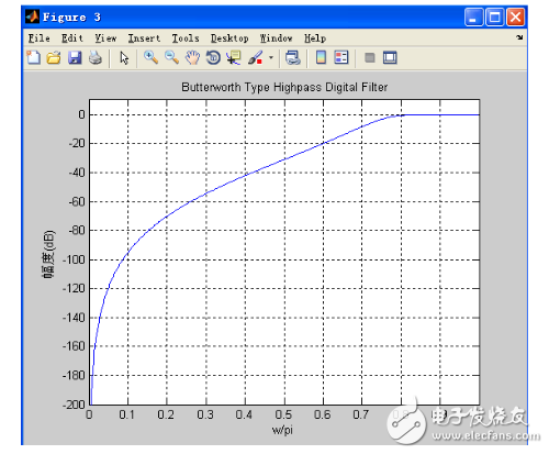
Detailed amplitude-frequency response
Analysis of the graph shows that the attenuation at 0.6 (i.e., 300 Hz) is 40 dB, while the attenuation at 0.8 (i.e., 400 Hz) is extremely small and should be less than 1 dB. It can be seen that this design meets the parameters of the required design.
In the process of debugging, it is found that the smaller the passband attenuation is, the better the performance of the filter is. The greater the resistance of the filter is, the better the performance of the filter is. The steeper the curve is, the better the selectivity is. Of course, the filter order used. The higher.
When the stopband attenuation becomes 40dB (previously 20dB), the waveform of the stopband is unchanged as shown below. Comparing the above figure, it shows that the attenuation becomes 40dB at the critical frequency of the stop band, and the curve becomes steep.
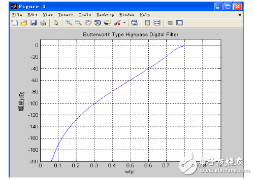
Detailed amplitude-frequency response (stopband attenuation is 40dB)
When the pass band becomes 5dB, when the stop band is unchanged, the waveform is as shown below. Comparing Figure 3-3, the attenuation at the passband becomes 5dB, and the curve is smoother.
Detailed amplitude-frequency response (passband attenuation is 5dB)
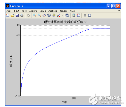
Theoretical calculation of digital filter simulationWp=0.8*pi;
Ws=0.6*pi;
OmegaP=2*1000*tan(wp/2);
OmegaS=2*1000*tan(ws/2);
Lamdas=OmegaP/OmegaS;
N=0.5*log10((10.^(20/10)-1)/(10.^(1/10)-1))/log10(lamdas);
The result of the % calculation is N=3.6947; therefore, take N=4%
Here is the transfer function for calculating high-pass Wn= 4.8890e+003 az=[0 0 0 0 1];
Bz=[1 2.613 3.414,2.613,1]; [Bbs,Abs]=lp2hp(az,bz,Wn) % is treated by bilinear invariance
[Bbz, Abz] = bilinear (Bbs, Abs, 1000); The result of the operation is: N = 3.6947;
In summary, the filter achieves the expected design goals in four steps: the sampling frequency is 1000 Hz, the passband critical frequency fp = 400 Hz, the passband attenuation is less than 1 dB (αp = 1); the stopband critical frequency fs = At 300 Hz, the attenuation in the stopband is greater than 20 dB (αs = 25), which performs better in the passband.
A servo encoder slip ring is a specialized device that is used in conjunction with a servo motor to allow for the transfer of electrical power and signals between the motor and stationary components. The slip ring consists of a number of metal contacts that are arranged in a circular pattern, and it is typically mounted on the shaft of the motor. As the motor spins, the contacts within the slip ring make contact with corresponding contacts on the stationary components, allowing for the transfer of power and signals.
The primary benefit of using a servo encoder slip ring is that it prevents wear and tear on the electrical connectors that would otherwise be subjected to constant movement. Additionally, it can help to improve reliability and performance by providing a more consistent flow of power and signals.
It is specially developed for servo motor and servo motor encoder slip ring. It has the characteristics of small size, light weight, low power consumption, and long life. The inner diameter of the slip ring is only 10mm, which can be used in a small space. The service life of the slip ring is more than 100,000 hours, and the power consumption is only 0.5W.
A servo encoder slip ring is a device that allows an electrical current to pass between rotating and stationary parts of a machine. It does this by using a set of brush contacts that rotate with the shaft, while stationary contacts are mounted on the housing. This allows for uninterrupted power and data transmission in applications where the stationary component cannot be easily moved.
Oubaibo is a leading manufacturer and supplier of servo encoder slip rings. They produce high-quality products that are reliable and durable, and they specialize in slip ring 18 wire, and commutators. Their products are used in a variety of industries, including aerospace, defense, medical, and manufacturing.
Servo Encoder Slip Ring,Slip Ring Korea,Slip Ring 18 Wire,Commutator With Slip Ring
Dongguan Oubaibo Technology Co., Ltd. , https://www.sliprob.com