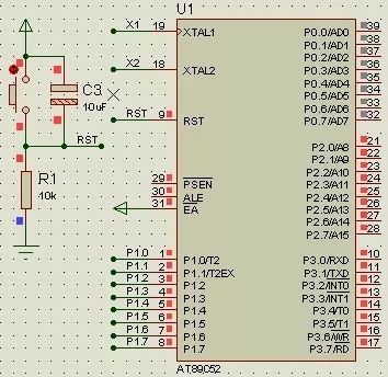
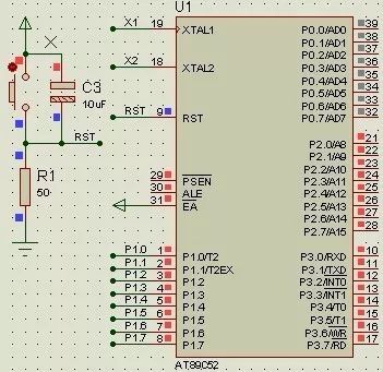
In the reset circuit, when R1 is 10kΩ, the RST pin is high. However, when R1 is 50Ω, RST becomes low. It’s clear that using a 10kΩ resistor is incorrect because it prevents the microcontroller from functioning properly during reset. The reason for this issue is that the RST pin contains a transistor that allows a small leakage current even when turned off. When the resistor is too large, this weak leakage current can still maintain a high voltage level, which leads to an unstable or incorrect reset state.
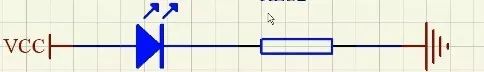
Second, calculating the LED series resistanceTypically, red LEDs have a forward voltage between 1.6V and 2.4V, with a current range of 2–20mA. The brightness increases significantly between 2–5mA, and beyond 5mA, the brightness remains relatively constant. This means that selecting the right resistor is crucial to avoid damaging the LED or making it too dim.
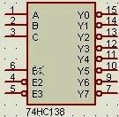
When the number of available I/O pins on the microcontroller is limited, you can expand the system by using an external chip such as the 74HC138 decoder. This allows you to control more devices without overloading the main controller.

Filter capacitors are divided into high-frequency and low-frequency types. High-frequency capacitors, usually 104 (0.1μF), help remove noise and protect the IC from interference like static electricity. They are typically placed between the power supply and ground.
Low-frequency capacitors, often electrolytic capacitors (100μF), are used to smooth out ripple in the power supply and store energy. These are usually placed near high-power components, such as USB ports, stepper motors, or LCD backlights. Their voltage rating should be at least twice the maximum voltage of the system.
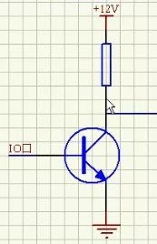
Fifth, the role of a bipolar junction transistor (BJT)1. Switch function: A BJT can act as a switch. For example, when the base is high, the transistor turns off the LED; when low, it turns it on. To calculate the current-limiting resistor, if the collector current is I, the base current is I/100 (assuming a gain of 100). The resistor value would be R = (5 - 0.7) / (I/100).
2. Amplification: The collector current is approximately 100 times the base current, allowing the transistor to amplify signals.
3. Level conversion: When the base is high, the transistor conducts, pulling the output low. When the base is low, the transistor is off, and the output goes high.
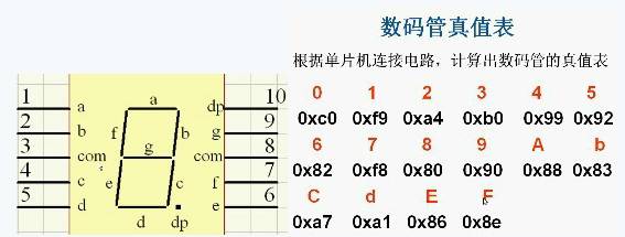
A seven-segment display forms numbers using segments a, b, c, d, e, f, g, and dp (decimal point). The specific lighting pattern depends on the segment configuration and the truth table provided above.
Seventh, current and voltage drive problemsMicrocontrollers have limited output capabilities. When driving heavier loads, additional driver chips like the 74HC245 are necessary to ensure proper signal integrity and performance.
Eighth, pull-up resistor selectionPull-up resistors are essential for ensuring stable logic levels. Key considerations include:
- Power efficiency: Larger resistors reduce current draw but may not provide enough drive strength.
- Drive capability: Smaller resistors allow more current but consume more power.
- High-speed circuits: Very large pull-up resistors can cause signal edges to become slow or distorted.
Typical values for pull-up resistors range from 1kΩ to 10kΩ. Pull-down resistors follow similar principles and are used to prevent floating inputs.
Ninth, crystal and reset circuitsCrystal oscillator circuit:
- Choose a crystal frequency based on your system needs (e.g., 6MHz, 12MHz, 11.0592MHz, 20MHz).
- Use two load capacitors (typically 20pF each) connected to ground.
- Measure the crystal using a multimeter by connecting the red probe to the oscillator pin and the black probe to GND.
Reset circuit:
The reset circuit initializes the microcontroller’s internal registers. For 51 MCUs, the reset time is about two mechanical cycles. You can find specific resistor and capacitor values for the reset circuit through online resources or datasheets.
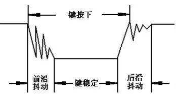
Tenth, button debounce and eliminationButtons are mechanical switches that can cause electrical noise (jitter) when pressed or released. This jitter can lead to multiple false trigger events. There are two common methods to eliminate this:
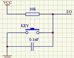
- Hardware debounce: Use a capacitor to short out high-frequency noise, stabilizing the signal.
- Software debounce: After detecting a key press, introduce a delay of 5–10ms before checking again. If the signal remains stable, it's considered a valid press.
For Nokia Glass,Mobile Front Glass Oca,Oca Front Glass,Oca Front Glass For Nokia
Dongguan Jili Electronic Technology Co., Ltd. , https://www.jlglassoca.com