Wind is a crucial parameter for understanding atmospheric dynamics and climate change. By analyzing wind data, we can observe atmospheric changes and predict future trends, enhancing our comprehension of energy, water, aerosols, and chemical cycles in the atmosphere. Meteorological analysis and global climate prediction rely heavily on accurate wind measurements. Currently, wind data are mainly collected through radiosondes, ground stations, ocean buoys, ships, aircraft, and satellites. However, these methods have limitations in spatial coverage and temporal resolution. Direct global 3D wind field measurements have become an important topic, and the World Meteorological Organization has emphasized the urgent need for high-resolution atmospheric wind data worldwide. Among existing technologies, Doppler wind lidar stands out as the only tool capable of directly measuring 3D wind profiles with the potential to provide global data [1].
Lidar has emerged as a powerful tool for atmospheric remote sensing. With advancements in laser technology, optical machining, signal detection, and data acquisition systems, lidar technology has evolved rapidly. Doppler wind lidar offers advantages such as practicality, high spatial resolution, and three-dimensional observation, which make it superior to other conventional techniques [2, 3, 4].
The newly developed 1064 nm direct detection Doppler wind lidar employs dual-edge technology to measure the three-dimensional wind field in the troposphere. This paper outlines the overall structure of the system and explains the functions of its components. It also presents and discusses preliminary results from tropospheric wind field measurements.
### 1. Overall Structure and Technical Parameters
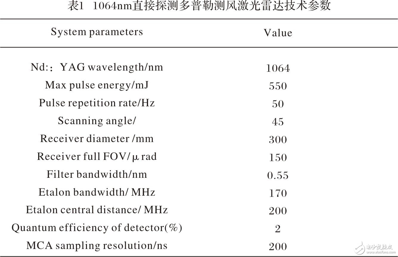
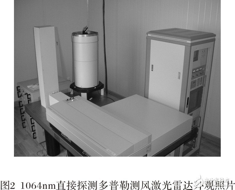
The 1064 nm direct detection Doppler wind lidar consists of a laser transmitter, a two-dimensional scanning unit, an echo signal receiver, a signal detection and data acquisition unit, and a control unit. The structural diagram and appearance photo are shown in Figure 1 and Figure 2 respectively. The main technical specifications are listed in Table 1.


The laser transmitter, echo signal receiver, and signal detection units are mounted on an optical platform to ensure stability. The Nd:YAG laser operates at a central wavelength of 1064 nm, offering high output power and strong aerosol backscatter. With a pulse repetition frequency of 50 Hz, the system can capture rapid wind changes, improving measurement accuracy. Internal laser injection ensures frequency stability.
The two-dimensional scanning unit, located on the roof of the lab, uses a large-diameter optical periscope made of two planar mirrors, horizontal and vertical rotation mechanisms, and a 1064 nm all-reverse dielectric coating. It can scan in all directions via software or manual control, with a horizontal range of 0° to 360° and a vertical range of 0° to 180°. The four-beam method is used for standard measurements, with scans in four cardinal directions (0°, 90°, 180°, 270°) at a 45° elevation angle.
The receiving telescope is positioned directly below the scanning unit, with an effective aperture of 300 mm. The primary mirror is coated with a 1064 nm full-reverse dielectric film, achieving 99% reflectivity. The received backscattered signal is coupled into an optical fiber, collimated, and filtered. A 20% reflection and 80% transmission beam splitter divides the signal. The reflected portion is detected by a photon counting detector, while the transmitted portion passes through two Fabry-Perot etalons, resulting in two signals of different intensities. These are split again and detected by separate photon counting detectors.
The data collected by the four detectors are converted into electrical signals, processed by a photon counting card, and stored and displayed in real-time by the industrial computer. The control cabinet houses an industrial computer running the system’s operation software, which controls the laser, scanning unit, and etalons via RS232 serial communication. Additional components include a CS100 controller, a scanning unit controller, a door control device, and a power supply for the monitoring and coaxial system.
### 2. Measurement of the Transmittance Response Curve of Dual Fabry-Perot Etalon
A key component of the 1064 nm Doppler wind lidar is the high-resolution dual Fabry-Perot etalon, which forms two semi-circular regions on a pair of substrates. The interferometer separates the spectral centers of the two channels based on coating thickness, creating an overlap in their transmittance curves. Since both etalons are fixed on the same substrate, their relative positions remain stable even with temperature fluctuations, ensuring consistent spectral spacing.
The transmittance curve of the dual Fabry-Perot etalon was measured using the CS100 control subroutine. Figure 3 shows the transmittance curve obtained from a 500-pulse cumulative average measurement on April 27, 2005, at 19:04. Channel one (real dots) and channel two (virtual dots) show a center interval of 228.2 MHz, with half-widths of 205.0 MHz and 224.3 MHz, respectively. The fitted curves have peak transmittances of 73.7% and 70.8%, aligning with the values in Table 1.
Environmental factors, mechanical vibrations, and long-term laser operation can cause drift in cavity length and frequency, affecting transmittance measurements. To evaluate performance, eight measurements were conducted between April 24, 2005, and May 15, 2005. The transmittance response curves in Figure 4 show that, despite a 21-day gap, the curves from the eight measurements align well, indicating excellent system stability.
Shanghai Janetec Electric Co., Ltd. , https://www.janetecelectric.com