At present, the terminal products of CMMB mobile TV applications are primarily mobile phones, PMPs, GPS devices, car TVs, and PCTVs. These systems share common characteristics such as compact size and strong internal interference. The presence of significant interference can severely impact the performance of CMMB mobile reception. System stability is not only dependent on chip performance, antenna quality, and PCB layout, but also on various types of spatial interference. If interference suppression is overlooked during the design phase, it can lead to substantial performance degradation. Designing a high-performance CMMB mobile digital TV terminal requires careful consideration of multiple factors, which will be explored in detail throughout this article.
Zhuosheng Microelectronics' CMMB receiver chip, MXD0251, integrates a self-developed silicon tuner and demodulator along with a 1.2V LDO. It only requires a 3.3V external power supply, reducing system cost and PCB space. The MXD0251 has a noise figure of less than 3.5dB across the UHF band. Its QPSK 0.5 mode carrier-to-noise ratio is 1.4dB, and its anti-digital analog adjacent-channel interference performance exceeds -50dB. The analog-to-analog same-channel indicator reaches -14dB, while its anti-co-channel interference uses advanced algorithms, offering excellent laboratory specifications. This ensures strong reception sensitivity and interference resistance at the chip level. In many cities, transmitted signals operate at higher frequencies, and in some areas, analog co-channel and adjacent-channel interferences are particularly strong. The MXD0251's superior interference suppression capabilities allow it to maintain stable reception under these complex conditions.
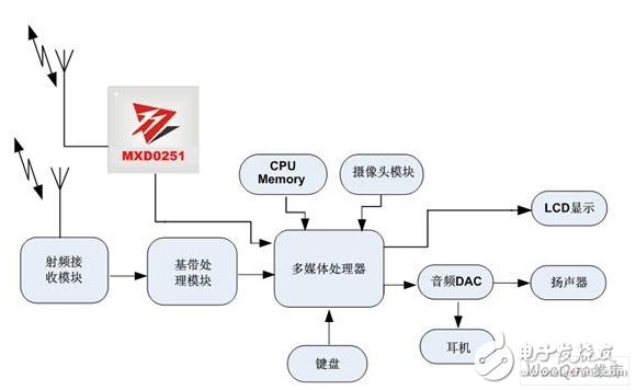
Figure 1: Architecture of the CMMB mobile digital TV terminal system based on MXD0251.
The signal chain starts with the antenna. The mainstream antennas used in handheld CMMB devices include whip antennas, ceramic built-in antennas, and active built-in antennas. For example, a whip antenna should have a length greater than 120mm and less than 200mm, ideally around 180mm. Once the antenna structure is determined, matching adjustments must be made. Antenna matching aims to reduce signal reflection and improve transmission efficiency. For the UHF receive band, it is recommended to reserve a matching network. A well-matched antenna should have a return loss of less than -6 dB across the operating band, an average gain of more than -4 dBi, and a radiation efficiency of over 40%. Data analysis from active tests helps determine whether further adjustments are needed to achieve conjugate matching or optimize specific frequency bands.
In summary, antenna matching helps balance performance across the entire operating frequency range, enhances overall receiving performance, or optimizes performance for specific bands. Figure 2 illustrates a practical case where the 500MHz match shows better resonance and a 5dB gain advantage over 700MHz.
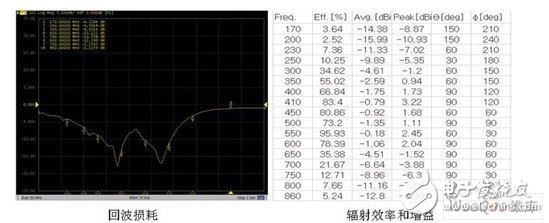
Figure 2: Antenna passive performance.
After selecting the antenna, the RF front end must be considered following matching. On the PCB, ensure that RF traces are as short as possible, avoid unnecessary bends, keep them away from digital signals, and use sufficient RF grounding. Even with these measures, various interferences may still couple into the RF section. Zhuosheng Microelectronics collaborates closely with leading CMMB antenna manufacturers to help customers choose the best antenna solution, design effective matching circuits, and perform antenna tuning together.
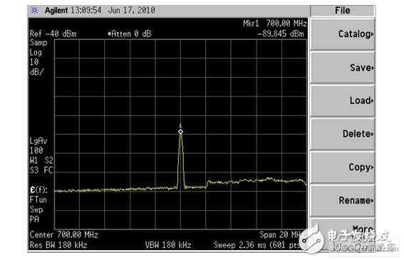
Figure 3: Single tone interference (Span: 20MHz).
Power supply and ground influence mainly manifest through the deterioration of the system’s noise floor. Therefore, it’s essential to ensure low power supply ripple. Since CMMB is a time-slotted system, current varies significantly between time slots. This means voltage fluctuations must be carefully managed. If using a DC-DC power supply, the layout trace should prevent any interference in the power loop. Additionally, the ground loop should be as short and clean as possible. If there is strong digital interference, it can be split on the ground loop to minimize its impact on the RF section.
The system clock, ADC, DAC, DDR clock, and certain signal lines can generate interference, producing strong spurs at specific multiples, as shown in Figure 3. At 700MHz, the interference reaches -89dBm, which can degrade the reception sensitivity at 698MHz. Sometimes, multiple spurs appear within the CMMB operating band, affecting several frequencies, as seen in Figure 4.
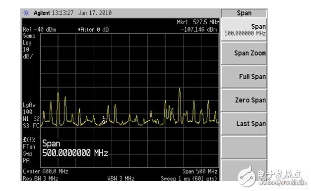
Figure 4: Multiple tone interference (Span: 500MHz).
MXD0251’s internal algorithm handles such situations by automatically detecting and filtering out spurs. These issues can often be avoided through proper layout. Keeping the interference source away from the RF section, ensuring the ground loop does not directly connect the RF trace layer, and minimizing the length of the interference path are key steps. However, different systems may encounter varying phenomena, so each case needs detailed analysis. Figure 5 shows a system with excellent spur performance—no spurs are present across the frequency band, resulting in a flat sensitivity curve.
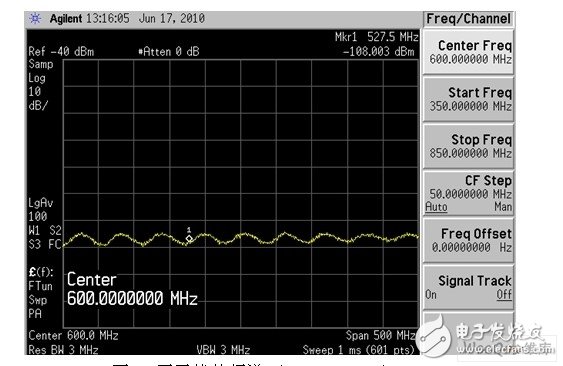
Figure 5: Interference-free spectrum (Span: 500MHz).
Coupled interference includes radiated interference from LCD FPCs, backlight interference from keyboards, and DC-DC switching noise. Among these, the LCD is typically the main source of interference, with noise coupling into the chip via the antenna and degrading reception performance. Screen interference often affects a wider frequency band, requiring EMI shielding and grounding on signal lines. Many cases show that below 600MHz, the screen FPC can cause 3–7dB of impact, with lower frequencies being more affected. Additionally, it’s important to suppress other wireless signals in the space at the RF front end, and adding a SAW filter is an effective solution.
In terms of coupled receiving sensitivity, good systems can differ from poor ones by tens of dB, which can directly affect the success or failure of a mobile TV product design. Zhuosheng Microelectronics offers both closed-loop and open-loop performance testing for customer prototypes, helping identify potential coupling interference. We can locate the interference source, analyze contributing factors, propose suppression strategies, and debug the final product to ensure optimal performance.
Single Phase UPS
Single Phase UPS provides backup power for small businesses, home offices, and critical equipment, ensuring continuous operation during power outages.
Features of single phase UPS include:
1. Automatic voltage regulation (AVR): This feature stabilizes the output voltage of the UPS, ensuring a constant and reliable power supply to the connected equipment.
2. Battery backup: Single phase UPS systems are equipped with batteries that provide backup power in the event of a power outage. This allows the connected equipment to continue operating without interruption.
3. Surge protection: UPS systems also offer surge protection to safeguard the connected equipment from power surges and spikes.
4. Monitoring and management: Some single phase UPS systems come with monitoring and management capabilities, allowing users to monitor the UPS status, battery level, and other important parameters.
5. Energy efficiency: Many modern single phase UPS systems are designed to be energy-efficient, helping users save on energy costs.
Usage of single phase UPS:
Single phase UPS systems are commonly used in homes, small businesses, and offices to protect computers, servers, networking equipment, and other critical electronic devices from power disruptions. They are also used in industrial settings to protect machinery and equipment from power disturbances.
Overall, single phase UPS systems play a crucial role in ensuring the reliability and availability of power to sensitive electronic equipment, making them an essential component of any power protection strategy.
Solar home power protection,Low voltage regulation,Gel battery backup,Single Phase Uninterruptible Power Supply, Power conditioning
Bosin Power Limited , https://www.bosinsolar.com