Power Integrity (PI) is a stable and reliable power distribution system (PDS) for board-level systems. In essence, the power supply and ground noise are effectively controlled when the system is in operation, and the chip is provided with sufficient energy in a wide frequency band, and the voltage fluctuation, radiation and crosstalk caused by the chip operation are sufficiently suppressed. This article will focus on the need for power integrity simulation. With the development of VLSI technology, the working voltage of the chip is getting lower and lower, the working speed is getting faster and faster, the power consumption is getting bigger and bigger, and the density of the board is getting higher and higher. Therefore, the power supply system is throughout. Stability within the operating band places higher demands.
The level of power integrity design directly affects system performance, such as overall machine reliability, signal-to-noise ratio and bit error rate, and important metrics such as EMI/EMC. Excessive board-level power channel impedance and synchronous switching noise SSNs can cause serious power integrity problems that can have a fatal impact on device and system operation stability. The PI design ensures that the board-level power channel impedance meets the requirements through reasonable planar capacitors, discrete capacitors, and planar split applications, ensuring that the board-level power quality meets device and product requirements, ensuring signal quality and stable operation of devices and products.
The interaction between power integrity PI and signal integrity SI: From the perspective of the entire simulation field, everyone has focused on signal integrity at first, but in fact power integrity and signal integrity are mutually constrained. . The power supply and the ground plane also provide a reference loop for the signal line while supplying power, which directly determines the return path, thereby affecting the integrity of the signal; the same processing method of signal integrity also brings different impacts to the power system, thereby affecting the power supply. The integrity of the design. So it is very beneficial to integrate power integrity and signal integrity. It is necessary for design engineers to enrich the knowledge of power integrity design after mastering the signal integrity design methodology.
The content of power integrity research: There are many contents of power integrity simulation, but the main aspects are as follows: 1: Simulation analysis of board-level power channel impedance, based on the full utilization of planar capacitance, the bypass capacitor is determined through simulation analysis. Quantity, type, location, etc., to ensure that the board-level power channel impedance meets the stable operation requirements of the device. 2: Simulation analysis of board-level DC voltage drop to ensure that the board-level power supply channel meets the device's voltage drop limit requirements. 3: Board-level resonance analysis to avoid the fatal effects of board-level resonance on power quality and EMI.
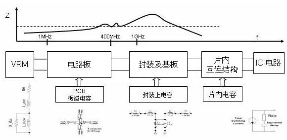
Power Distribution System (PDS): The above picture is a classic power distribution system characteristic diagram, I believe everyone is familiar with. From this picture, we can divide the entire power supply band into several parts. In the low frequency band, the power supply noise is mainly filtered by the power conversion chip VRM. In the frequency range from a few MHZ to a few hundred MHZ, the power supply noise is mainly filtered by the board-level discrete capacitor and the power ground plane pair of the PCB. In the high frequency part, the power supply noise is mainly filtered by the power ground plane pair of the PCB and the high frequency capacitance inside the chip. When we are doing simulation, the simulation accuracy of the low frequency and high frequency parts is still inaccurate. The truly meaningful frequency band is mainly in the frequency band of several MHZ to several hundred MHZ.
Target impedance Ztarget Let's talk about the target impedance Ztarget that everyone is familiar with. The author believes that this target impedance is a useful but inaccurate standard in power integrity simulation.
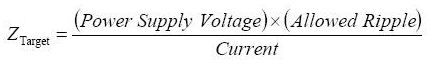
Where: Ztarget target impedance Power Supply Voltage is the operating voltage Allowed Ripple is the allowable operating voltage ripple coefficient Current is the operating current, currently this value is replaced by 1/2 of the maximum current.
Everyone knows that when testing power supply, it mainly tests ripple and noise, but it is still difficult for the industry to perform time-domain ripple noise simulation through software. Some large companies have already tested the noise model of the chip and then used this. The model is directly simulated, and the result is power supply noise, but it is still in the exploration stage, which is not used for promotion. Instead, it simulates the power supply impedance of the power distribution system. Their relationship can be contacted by V=R/I. Therefore, if the impedance curve is still simulated, the test and simulation cannot form a closed loop.
The standard of this target impedance is used to measure whether this impedance curve can meet the requirements, but if you think about it, there are still many problems with this standard. For example: How big is the current here? The actual board power consumption is a dynamic power consumption, which is a misleading change.
In the entire frequency range of the board, the use of a uniform target impedance value is certainly unreasonable. It should be the frequency band and the standard is different. Although these problems exist, this standard is still very useful, and the quality of the power plane can be measured by this standard. Just like the current timing calculations, we basically calculate the timing through the formula, which is called static timing analysis. Although this static timing analysis is not considerate for power supply fluctuations, ISI, SSN, etc., that is to say, the calculation results are not accurate, but it is useful to measure the interface timing. Therefore, the author believes that the target impedance is a useful and inaccurate standard. There is a lot of information about the capacitors. Here is a brief introduction. The panel capacitors that are important in PI simulation will be introduced next time.
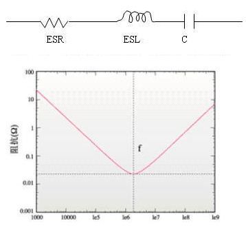
Capacitance is more than just a capacitor: at high frequencies, the capacitor can no longer be viewed as an ideal capacitor, but should take into account its parasitic effects. Usually the parasitic parameters of the capacitor are ESR, ESL. The series RLC circuit resonates at f. The curve is shown below. In the figure, f is the series resonant frequency (SRF), which is capacitive before f, and after f, is inductive, equivalent to an inductance, so when selecting the filter capacitor, the capacitor must be operated before the resonant frequency.
In the simulation, since the current VRM model is basically inaccurate, the low-frequency filtering is done by the DC/DC power conversion chip. Generally, the low-frequency impedance curve below 300K is inaccurate. The upper limit of the frequency range generally takes the cutoff frequency of the signal fknee = 0.35 /Trrise, where Trise is the signal rise time.
But also understand that if you only do board-level power integrity simulation, you can consider 1G at most, because after 1G, you need to rely on the internal capacitor to filter. When doing board-level simulation, there is no chip inside. The model, so the simulation of the high frequency part is also inaccurate. Of course, if you have information inside the chip, you can also use DW-PACKAGE-BOARD co-simulation with software such as SIWAVE, and the high-frequency part will be accurate. Therefore, in many cases, the low-frequency simulation does not produce negative feedback from the power supply, and the high-frequency simulation does not show the on-chip capacitance. We should not regard the simulation result as an absolute value. It can be regarded as a relative value, through the selection and placement of decoupling capacitors. Methods such as power and ground plane segmentation are used to optimize impedance. I wish you all the flexibility in your simulation.
U Ground Screw :
Abnormal shape Ground screw including many kinds of designs ,which are not same as standard design of ground screw with nut or flange ,usually add some special assist parts ,or special design of ground screw .
Materlal of hot dip galvanized ground screw :Q235 carbon steel
Diameter of pipe : 48 mm,60 mm,68 mm,76 mm,89 mm,114 mm
Length of ground screw : 550-6000 mm
Thickness of pile : 2.50-4.0 mm
Surface treatment : Hot dip galvanized,DIN EN ISO 1461-1999,thickness of coating :more than 80micron
Mainly including : no pipe-ground screw, field ground screw ,no-pipe ground screw with nut ,flange ground screw double flange pile ,twist pile ground screw,ground anchor screw,screw pile,galvanizing ground screw
Usage : Farm or garden fence,tent,solar energy system ,PV Mounting ,advertising board or banner ,simple house &


U Type Ground Screw,U Type Fence Post Anchor,U Shape Ground Screw,Ground Anchor
BAODING JIMAOTONG IMPORT AND EXPORT CO., LTD , https://www.chinagroundscrew.com