A DC motor is a rotating electrical machine that converts DC electrical energy into mechanical energy (DC motor) or converts mechanical energy into DC electrical energy (DC generator). It is a motor that converts DC power and mechanical energy to each other. When it is used as a motor, it is a DC motor that converts electrical energy into mechanical energy; when the generator is running, it is a DC generator that converts mechanical energy into electrical energy.
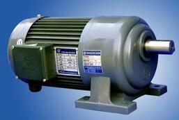
The working principle of the DC motor is that a ring-shaped permanent magnet is fixed inside, and the current generates an Amperage through the coil on the rotor. When the coil on the rotor is parallel to the magnetic field, the direction of the magnetic field that continues to be transferred will change, so the end of the rotor at this time The brush is in alternating contact with the converter, so that the direction of the current on the coil also changes, and the direction of the Lorentz force generated does not change, so the motor can maintain one direction of rotation.
The working principle of the DC generator is to change the alternating electromotive force induced in the armature coil by the commutation function of the commutator and the brush to change the DC electromotive force when it is taken out from the brush end.
The direction of the induced electromotive force is determined according to the right-hand rule (the magnetic line is pointing to the palm of the hand, the thumb is pointing to the direction of movement of the conductor, and the other four fingers are pointing in the direction of the induced electromotive force in the conductor).
The direction of the conductor's force is determined by the left-hand rule. This pair of electromagnetic forces forms a moment acting on the armature. This torque is called electromagnetic torque in the rotating machine. The direction of the torque is counterclockwise, in an attempt to rotate the armature counterclockwise. If this electromagnetic torque can overcome the resistive torque on the armature (such as the resistive torque caused by friction and other load torque), the armature can be rotated counterclockwise.
DC motor control principleFor ordinary DC motors. Its control method is relatively simple. Simply add the appropriate voltage to the two control lines of the motor to turn the motor. The higher the voltage, the higher the motor speed. For speed regulation of DC motors. A method of changing the voltage may be employed, or a PWM speed adjustment method may be employed. PM speed regulation is to make the voltage applied to the two ends of the DC motor a square wave. The voltage applied across the motor is continuously changing between VLoad and OV. The corresponding motor voltage waveform is shown in Figure 1:
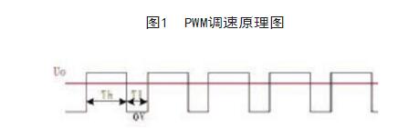
At this time, the average voltage Uo=Th/(Th+T1)*VLoad applied to both ends of the motor can change the ratio of Th and T1 by adjusting the duty ratio of the PWM. In this way, the average voltage applied across the motor can be adjusted by PWM to change the speed of the motor. Similar to a stepper motor. It is not possible to directly connect the IO of the microcontroller to the lead of the DC motor, but to increase the drive circuit between the two. The L298N motor driver chip can also be used to drive the DC motor.
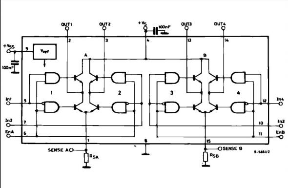
L298N chip dataConstant voltage constant current bridge type 2A driver chip L298N: L298 is a product of SGS company. The more common one is the L298N of the 15-pin Mult iwatt package. The internal also contains a 4-channel logic driver circuit. It is convenient to drive two DC motors or one two-phase stepper motor.
The l298N chip can drive two two-phase motors. It is also possible to drive a four-phase motor. The output voltage can be up to 50V. The output voltage can be adjusted directly through the electricity: the signal can be directly provided by the IO port of the single-chip microcomputer: and the circuit is simple and convenient to use.
The L298N accepts the standard TTL logic level signal VSS, which can be connected to 4.5 to 7 V. The 4-pin VS is connected to the power supply voltage. The VS voltage range VIH is +2.5 to 46 V. The output current can reach 2.5A, which can drive the inductive load. The emitters of the 1 and 15 leg lower tubes are separately led out to access the current sampling resistor. A current sensing signal is formed. The L298 can drive 2 motors. The motor can be connected separately between OUT1, OUT2 and OUT3, and OUT4. In this experimental device, we chose to drive one motor. The 5, 7, and 10.12 pins are connected to the input control level. Control the forward and reverse of the motor. EnA, EnB is connected to the control enabler to control the motor's stall. Table 1 is the L298N functional logic diagram.
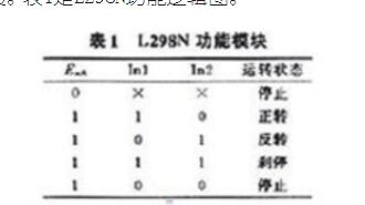
The logic diagram of In3.In4 is the same as in Table 1. Table 1 shows that EnA is low. The input level is active for motor control. When EnA is high, the input level is high and low. The motor is either positive or negative. The same low level motor stops. The same high level motor brakes.
The following is the system structure diagram of L298N
Int in1=13;
Int in2=12;
Int in3=11;
Int in4=10;
/ / The above defines the four control terminals on the board, 12 groups, 34 groups
Int speedPinA=6;
Int speedPinB=5;
//The PWM pin is defined above
Void setup()
{
pinMode(in1,OUTPUT);
pinMode(in2,OUTPUT);
pinMode(in3,OUTPUT);
pinMode(in4,OUTPUT);
//The following program starts with the control terminal high and the motor remains stationary.
digitalWrite(in1,HIGH);
digitalWrite(in2,HIGH);
digitalWrite(in3,HIGH);
digitalWrite(in4,HIGH);
}
Void loop()
{
//The motor is turning forward
_mRight(in1,in2);
_mRight(in3,in4);
/ / Read the value of the potentiometer, and then control the motor speed through the PWM output
Int n=analogRead(A0)/4;
_mSetSpeed(speedPinA,n);
_mSetSpeed(speedPinB,n);
}
Void _mRight(int pin1, int pin2)//The motor turns right, whether the motor is turning right or left depends on the wiring of the motor end and the order of the control pins.
{
digitalWrite(pin1,HIGH);
digitalWrite(pin2, LOW);
}
Void _mLeft(int pin1, int pin2)//ibid
{
digitalWrite(pin1, LOW);
digitalWrite(pin2,HIGH);
}
Void _mStop(int pin1, int pin2)//emergency braking, the actual is to short the two ends of the motor
{
digitalWrite(pin1,HIGH);
digitalWrite(pin2,HIGH);
}
Void _mSetSpeed(int pinPWM, int SpeedValue) / / control speed, in fact, is the enabler of the intermittent control 298N, the hand shake is powerful, you can try it with a button, it is estimated that the motor speed can be controlled, O (∩_∩)O~
{
analogWrite(pinPWM,SpeedValue);
}
Dual Fuel generator assembly by dual fuel engine, alternator, radiator, controller, base frame;
. Dual Fuel engine brand: CRRC, CSSC, CSI, SWT
. World famous AC alternator brand: Stamford, Leroy Somer, Mecc Alte, Marathon, Faraday, SWT
. World famous genset controller brand: Deepsea, ComAp, Deif, Heinzmann, Woodward
. Gas Control System: Ignition system, Gas Throttle System, Ga Mixer System, Gas Train Valve System
. Start Battery system
. Optional for Remote Cooling system with CHP & CCHP Control
. CHP- Combine with Heat and Power Electrical system
. Maximum 80% Natural gas, 20% Diesel fuel
.CCHP- Combine with Cold, Heat and Power electrical system
Dual Fuel Genset,Dual Fuel Generator,Dual Fuel Power Plant,Diesel & Gas Generator
Guangdong Superwatt Power Equipment Co., Ltd , https://www.swtgenset.com