introduction
In 1890, physicist Bryan GH discovered that the flexible hemisphere can measure the rotating Bryan GH theory. In 1988, the Muller research team at the University of California, Berkeley invented a silicon electrostatic motor with a rotor diameter of 60-100 μm. At this point, MEMS gyros are small in size, light in weight, low in power consumption, suitable for mass production, and have been valued by various developed countries, and have been researched and applied. Rotating vibration structure, rotating disk structure, vibration disk structure, line vibration structure, orthogonal line vibration structure (vibration plate structure, vibration beam structure, vibration tuning fork structure and accelerometer vibration structure) and non-orthogonal line vibration structure (thin wall hemisphere) Resonance, resonant cylindrical structure and resonant ring structure) MEMS gyros appear one after another. According to the analysis of foreign researchers, there are more than 2,000 possible combinations of different working principles, technical solutions and processing techniques of MEMS gyro. At the same time, the advancement of system technology and the improvement of the technological level have also brought new opportunities for the development of MEMS inertial technology. The performance of MEMS inertial instruments has been rapidly improved in a short period of several decades, and has been widely applied to varying degrees. . Among them, the consumer MEMS gyro mostly adopts the traditional tuning fork structure, which cannot meet the application requirements of high precision and special environment.
In foreign countries, the military high-end MEMS gyro technology route and the commercial MEMS gyro technology route are completely different. The military high-end MEMS gyro technology route is basically a fully symmetrical structure with good environmental adaptability. The Micro Defense PNT (Micro-PNT) project of the Defense Defense Advanced Research Projects Agency (DARPA) focuses on the development of multi-ring resonant disk gyro (DRG) and micro hemisphere gyro (VRG) with good results. In 2015, DARPA's new Advanced Inertial Microsensor (AIMS) project emphasized the development of only two- or three-dimensional CVG-II gyros with fully symmetrical structure. British BAE Systems began the development of resonant ring gyroscopes in the 1990s. The products have been used in batches for APKWS guided bombs, NLAW anti-armor weapons, and 155 mm Raytheon guided cannonballs and satellites. Compared with the current MEMS gyro technology such as tuning tuning fork type, flat vibration type and housing vibration type, it has high precision, high dynamic range and strong anti-overload capability. It can directly measure the rotation angle and avoid the dynamics brought by the subsequent integration circuit or algorithm. The unique advantages of error and switching between angle and angular rate modes and easy mass production have become effective platforms for a variety of medium and high precision weapon carrier platforms, especially for high dynamic rotary guided projectiles and inertial navigation systems for rockets.
Developed countries have not stopped the development of high-performance ring-shaped fully symmetrical structure MEMS inertial devices. They have been tested in actual combat and realized the "medium high precision, low cost, high reliability, high volume, medium" of fully symmetric annular solid wave gyro. End military use". Moreover, a new generation of high-precision silicon micro hemispheres and fully symmetrical annular solid wave gyros and their multi-gyro array integration technology are emerging.
01
Development of solid wave gyro to MEMS gyro
1 Solid wave theory and Coriolis gyro
In 1960, the solid wave gyro experienced the development and upgrade of metal hemispherical resonator gyro (HRG) and quartz HRG, and evolved into a three-dimensional and two-dimensional resonant gyro based on MEMS technology. Finally, the development direction and technical route of high-end MEMS resonant gyro were established.
The basic principle of a solid wave gyro is that the rotational angle of the standing wave excited in the rotating axisymmetric object (resonator) is proportional to the projection of the input angular rate on its axis of symmetry. This principle utilizes the elastic wave inertia effect in a rotating axisymmetric object, that is, the standing wave precession characteristic.
As shown in FIG. 1, the mass P is fixed in the xoy plane of the rotating coordinate system, and if it moves in the x-axis direction at a speed v relative to the rotating coordinate system, the rotating coordinate system rotates around the z-axis at an angular velocity ω. The Coriolis force generated by the Coriolis effect on the mass P is: Fcor = 2 m (v × ω). Where m is the mass of the mass P.
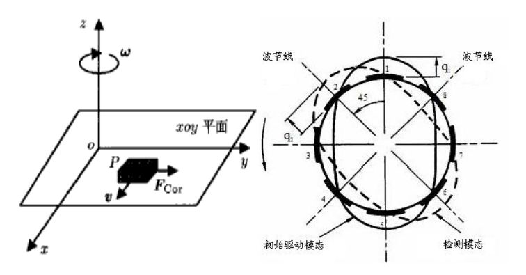
Figure 1 Working principle of vibrating gyroscope
It can be seen that the Coriolis force Fcor is proportional to the input angular velocity ω on the mass P and causes the displacement of the mass in the y-axis direction (information of the input angular velocity). In summary, the vibrating component of the vibrating gyroscope is driven to rotate in a direction perpendicular to the first vibrating mode in a first vibrating mode (also referred to as a driving mode, as shown in FIG. 1 as the mass P moves along the x-axis). When the angular velocity is input (as shown in Fig. 1 along the z-axis rotational angular velocity), the vibrating component generates a second vibration mode of the vertical first vibration mode due to the Coriolis effect (also called the sensitive mode, as shown in Fig. 1 The displacement produced by the y-axis, which is directly proportional to the angular velocity of rotation. Vibrating gyros of various structural forms actually use the same principle.
The resonant ring gyroscope consists of a vibrating ring, a support beam, and a drive and detection control electrode. Based on the consideration of symmetry, at least eight spring beams are required to balance the structure and have two bending modes of the same natural frequency, as shown in FIG. 2 . Under the action of electrostatic force (or electromagnetic force), the resonant ring performs first-order bending mode vibration in a plane with a fixed amplitude and ellipse. When it rotates around the normal axis, the Coriolis force will transfer the vibration energy to the phase difference. The 45° second-order detection vibration mode, the vibration amplitude of the second-order detection vibration mode is proportional to the input angular rate, and can be detected by the change of the capacitance.
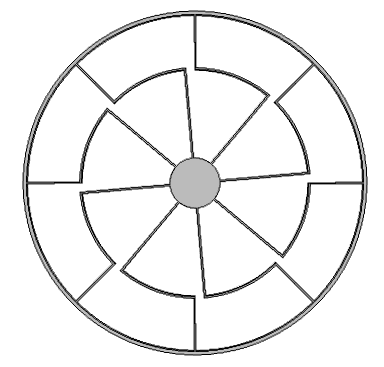
Figure 2 Resonant ring structure gyro
2 Evolution from HRG to MEMS planar gyro
HRG is a concrete implementation of solid wave gyro. In 1965, Dr. David L completed the theoretical modeling analysis of fully symmetric HRG. In 1975, the United States Delco developed the world's first hemispherical resonant gyro with an accuracy of 50 (°) / h; later using high Q quartz material, the accuracy of 1980 reached 1 (°) / h. In 1996, Litton acquired Delco to develop a high-performance quartz HRG for the Hubble Space Telescope project. The index is: 0.5 (°) / s, zero bias stability is 0.00008 (°) / h, angle random walk 0.00001 (°) / h1/2.
In 2000, 2009, and 2011, Kristiansen and Shatalov and Ren Shunqing and other scholars established the equivalent equations of cylindrical resonant gyro and hemispherical resonant gyro, respectively, and thus used the energy principle in bookshell mechanics to give two kinds of structural vibratory gyros. The dynamic equations make great contributions to the research and development of cylindrical resonant gyros and hemispherical resonant gyros.
In 2000, Litton was acquired by Nog, which developed more than 500 HRG gyros for major aerospace missions such as the US Venus exploration and comet impact. Studies have shown that hemispherical resonant gyros have almost no physical limitations in performance and have great development potential. However, the hemispherical resonant gyro is a three-dimensional structure, the processing process is complicated, the manufacturing is difficult, and low-cost mass production cannot be achieved. There are many structural changes in the development process, resulting in a variety of two-dimensional structures, as shown in Figure 3. These two-dimensional structures are well suited for current MEMS manufacturing processes and enable low-cost mass production.
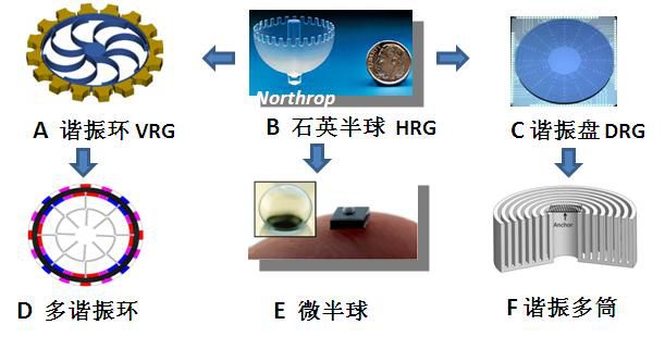
Fig. 3 Development and evolution of hemispherical resonator gyro
The resonant ring gyro of Figure 3(A) is a simplified form of a hemispherical gyro. British Goodrich Company and BAE Company (Atlantic Inertial Systems Branch) have been working on the research of ring gyroscope since the early metal tube structure VSG-1. Since the 1990s, the development of resonant ring gyroscope has gradually evolved to New piezoelectric material ring gyroscope VSG-5. Its series of shelf products CRS03, CRG20, CRM100/200 and other products occupy a large share of the world's high-end MEMS gyro market, and are used in the missile-prevention weapons of the United Kingdom, the United States, Sweden, Turkey and other countries. At present, the fourth generation has been developed, and the latest product gyro bias stability has reached 0.1 (°) / h 1/2.
Many universities in the United States have also carried out research on new fully symmetrical structure gyros. Among them, Dr. Ayazi of the University of Michigan completed the world's first MEMS full-symmetric ring gyroscope in 2000, and the gyro bias stability reached 5 (°) / h. In 2008, Dr. Zaman performed a resonance star structure improvement, and the gyro bias stability has reached 2.5 (°) / h. Figure 3(c) shows a resonant disk gyro jointly developed by several schools, such as Berkeley University, with a diameter of 0.6 mm and a thickness of 20 μm. The sample accuracy is 3.27 (°) / h. Figure 3(F) is a multi-barrel resonant rate integrated gyro developed by the University of Michigan with a resonant frequency of 3 kHz, a Q value of 72000, a zero offset of 129 (°) / h, and an angular random walk coefficient of 0.09 (°) / h1/ 2.
02
Development status of foreign military MEMS resonant gyro
1 Evolution from HRG to MEMS planar gyro
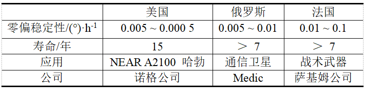
In 1996, the United States first applied HRG attitude-sensitive units in space, with about 125 sets of accumulated flights of 2 × 10⁷h. Russia, France and other countries have developed rapidly and have achieved good results. HRG is considered by the international inertia community to be the most ideal device widely used in various types of carrier strapdown systems in the 21st century. The foreign HRG pairs are shown in Table 1.
Table 1 Comparison of foreign HRG development levels
2 MEMS resonant gyro development status
The MEMS resonant ring gyro is derived from quartz HRG and is a simplified structural form of HRG. Compared with HRG, in addition to maintaining HRG sensitive structure with full symmetry, high precision and good environmental adaptability, it is suitable for applications in aerospace and military fields with high performance requirements and harsh environment. It also has simple structure, reliable, small size and convenient batch. Integrated manufacturing. At present, the resonant ring gyro has been developed to the fourth generation of products, as shown in Figure 4, gradually transforming from mechanical gyros to MEMS silicon-based gyros.
First generation resonant ring gyroscope
The first generation of resonant ring gyroscope products adopts the ceramic structure of the cylindrical shell, which is similar to the traditional gyro. The development platform is mainly a mechanical processing platform. Its characteristic is that the sensitive structure is prepared by mechanical processing, large in volume, strong in sensitive signal, and adopts traditional tissue processing technology.
Second generation resonant ring gyroscope
The second generation of resonant ring gyroscopes simplifies the structure through advances in drive and inspection technology, but similar to the first generation, the development platform is primarily a machining platform.
Third generation resonant ring gyroscope
The third generation of resonant ring gyroscope products adopts new MEMS processing technology. Through electromagnetic excitation and current detection, the volume of the gyro is reduced and the performance is greatly improved. Its characteristics are: a) The sensitive structure is processed by MEMS technology, and the frequency difference between the two resonant modes is adjusted by using the laser trimming technique (frequency difference <1 Hz), and the energy conversion capability is enhanced by the matching between the two modes. , to improve device performance; b) the use of microelectronic packaging technology (metal shell) and traditional assembly technology (core assembly) for product packaging. Its development platform is a combination of mechanical processing platform, microelectronic platform and MEMS platform.
Fourth generation resonant ring gyroscope
The fourth generation of resonant ring gyro products adopts a new MEMS processing technology, which removes the core structure inside the gyro, and greatly improves the performance, volume and power consumption of the gyro through capacitive excitation, capacitance detection, trimming and other technologies. . Its device features are:
a) sensitive structures are processed using MEMS technology;
b) using the trimming technique to adjust the frequency difference (<0.1 Hz) between the two resonant modes, and enhance the energy conversion capability by matching between the two modes to improve the performance of the device;
c) using a dedicated processing circuit in combination with a microprocessor for signal detection and processing;
d) Gyro package is used in MCM package form.
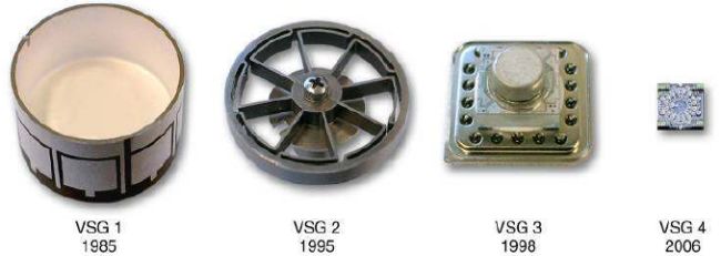
Figure 4 Development history of silicon micromachined gyroscope
The fourth generation of resonant ring gyroscope development platform is a combination of microelectronic platform and MEMS platform. The technical characteristics of the product are also the development trend of the mainstream MEMS gyroscope products in the world. The main features include:
a) The sensitive structure is packaged in high vacuum with a high Q value;
b) adjusting the sensitive structure to improve the inherent characteristics and yield of the sensitive structure;
c) use special processing circuits to improve signal processing and sensitive structure adjustment capabilities;
d) using a microprocessor to enhance the internal compensation and environmental adaptability of the product;
e) Using MCM integrated packaging technology to reduce volume and improve stability;
f) Adopt system-level design to match the various parts of the gyroscope such as sensitive structure, processing circuit, microprocessor, and package, give full play to the technical advantages of each part of the system, make up the technical bottleneck between each other, and realize the system performance. maximize.
Silicon-based MEMS gyroscopes with the above characteristics have gradually matured from the emerging, and then toward the system integration road, to achieve the application of systems such as MEMS inertial measurement unit (IMU).
BAE Systems of the United Kingdom has implemented the MEMS IMU series with MEMS resonant ring gyro. The smallest volume is only 16 cm3. It is the smallest IMU unit in the world. It can be implanted into the soldiers' boots to achieve individual time. navigation. BAE's MEMS IMU serialization is shown in Figure 5. This type of gyro has ultra-high anti-high-impact capability and is controlled by a digital closed-loop circuit. By changing the parameters of the scale factor control loop, the range is 600~12 000 (o Adjustable within the range of /s, the bias stability is <0.1 (°) / h. The resonant ring gyroscope produced by BAE has two modes: angular rate and rate integral. The developed products are used in high-speed rotating bombs, medium-range missiles and US 155 mm guided archery and other weapon systems. The ESA research space for MEMS resonant ring gyros has been verified in-orbit in the 2012 Cryosat2 satellite and will be used in the 2018 launch of the Mars rover (ExoMars rover).
Japan Silicon Sensing Systems Co., Ltd. (SSS) has been engaged in the development of MEMS resonant ring gyroscopes. The latest product has a zero bias stability better than 0.06 (°) / h, and the angular random walk is better than 0.01 (°) / h 1/2. The highest level of the top.
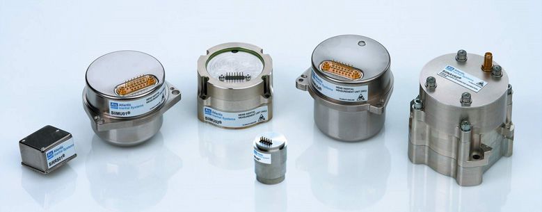
Figure 5 BAE Systems Inc. Serialized MEMS IMU
Development status of 3 MEMS dish-shaped gyro
The MEMS dish-shaped gyro is the gyro device with the highest reporting accuracy in the current MEMS gyro, and it is also one of the most popular planar MEMS gyro structures.
As early as 1994, the hemispherical resonator gyro developed by Boeing Company was applied to Boeing's TDRS HIJ satellite. It was used in the second generation TDRS satellite in 2000, and the MEMS gyro was developed at the same time. The development route is shown in Figure 6.
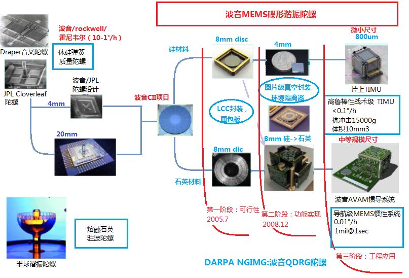
Figure 6 Boeing's high-performance MEMS gyro development roadmap
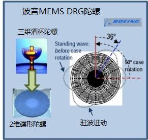
Figure 7 MEMS dish gyro
Based on the research basis of HRG and other MEMS gyros, Jet Propulsion Laboratory and Boeing Company combined HRG and tuning fork MEMS gyro to propose a multi-ring structure MEMS dish-shaped gyro solution, namely multi-ring resonant disk gyro. The multi-ring resonator disk gyro includes a series of concentric discs, each concentric ring being connected to the center disc by a micro-beam, as shown in FIG. The multi-concentric ring structure reduces the radius stiffness, and its multi-concentric ring design realizes the full symmetry of the structure. The sensitive structure of the fully symmetrical structure can reduce the orthogonal coupling of the driving and detecting modes, thereby realizing the silicon microgyroscope driving mode. Matches with the detected modality. The multi-ring design not only greatly increases the electrode area, but also improves the detection and driving capacitance, thereby improving the detection sensitivity of the gyro and increasing the effective quality. Increasing the effective quality is very important for reducing the noise level. Multi-ring and multi-detection are adopted. The electrode solves the difficulty of low signal-to-noise ratio of the ring gyro. With the support of the DARPA Navigation Integrated Microgyroscope (NGIMG) project in the United States, the research on the resonant disk gyro has made a breakthrough. The resonant disk gyro based on 8 mm diameter silicon material achieves zero deviation stability better than 0.01 (°)/ h, the angle random walk is better than 0.002 (°) / h 1/2. In order to further narrow the performance gap with HRG, a resonant disk gyro based on 8 mm diameter quartz glass material or larger is under development. The expected goal is to increase the Q of the resonant disk gyro by one to two orders of magnitude, and the angular random walk is increased by an order of magnitude.
In 2013, the MEMS Resonator Gyro development team was spun off from Boeing and Jet Propulsion Laboratory and established SIM (Sensor in Motion), specializing in R&D and production of resonant disk gyros. Relying on more than 30 years of accumulated technology and experience, the company produces high-performance low-cost navigation-grade resonant disk gyros, which represent the highest level of MEMS gyro and achieve laser and fiber optic gyroscope performance. The volume of the compass based on the resonant disk gyro is 180 cm3 and the mass is 0.11 kg.
In the fields of military and aerospace, MEMS gyros, resonant ring gyro and multi-ring disk-shaped resonant disk gyro have the highest level of productization and are widely used in weapons and equipment.
03
Future high-end MEMS gyro development direction
1 US high-end MEMS gyroscope development plan
The United States and other western developed countries attach great importance to the development of MEMS inertial systems and devices. DARPA has developed many specific plans for the development of MEMS inertial devices, which have important reference value. The DARPA MTO has two gyro research projects at the device level, one for NGIMG and one for the Micro Rate Integral Gyro (MRIG) project.
The NGIMG project develops low-power miniature angular rate sensors that support individual soldiers, vehicles, drones, and large combat platforms without GPS signals. The research objectives are: zero deviation stability 0.01 (°) / h, angle random walk 0.001 (°) / h 1/2, Boeing company multi-ring resonance disk gyro, Figure 3 (C) is the key development program.
In 2011, DARPA launched the MRIG project to develop micro hemisphere gyros, as shown in Figure 3(E), to provide support for highly dynamic space weapons. The research objectives are: range 15000 (°) / s, zero bias stability 0.01 (°) / h, scale factor repeatability 0.01ppm. The project encourages structural innovation, with eight universities in the United States participating in the development of a variety of innovative structures and 3D production process solutions.
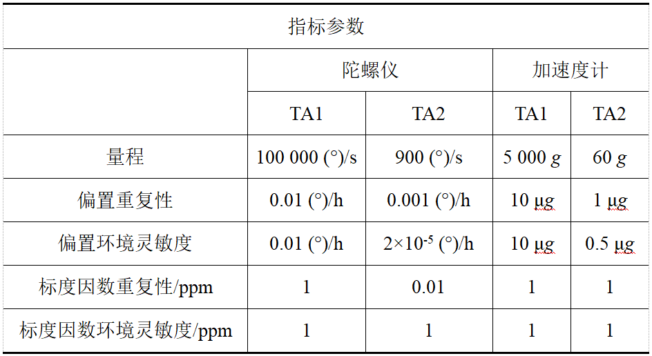
In 2015, we developed a new advanced low SWaP+C advanced inertial micro-sensor (AIMS) for the advanced inertial device DARPA new start-up precision robust inertial guided munition (PRIGM) project, which has a high dynamic range in high impact and high vibration environments. Low-noise, high-precision inertial devices, detailed indicators are shown in Table 2 and Table 3. Among them, TA1 is a high dynamic environment device index, and TA2 is a high precision and high stability device index.
Table 2 DARPA Advanced Inertial Microsensor AIMS Development Indicators (a)
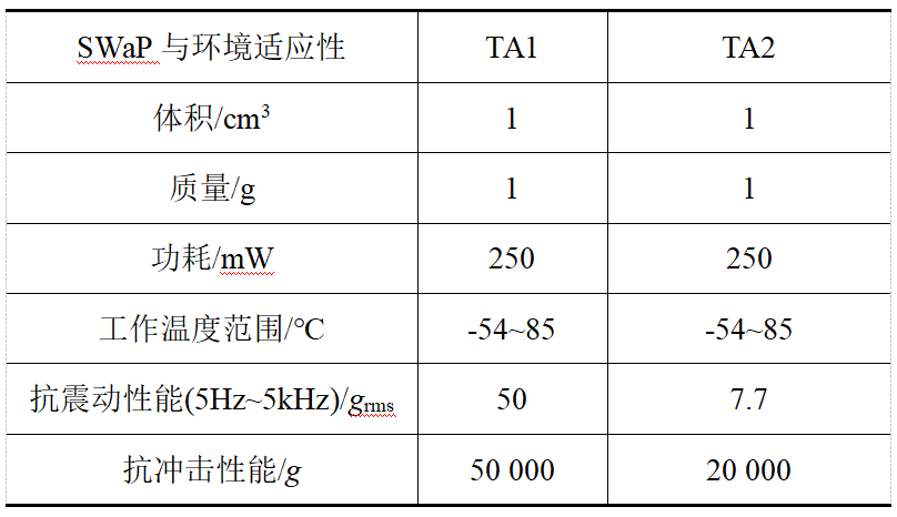
Table 3 DARPA Advanced Inertial Microsensor AIMS Development Indicators (b)
As shown in Figures 8-10, the three gyro development directions supported by the AIMS project are: 1) rate integral gyro; 2) light detection MEMS gyro; 3) on-chip optical waveguide gyro. At the same time, DARPA emphasizes that it only supports the development of highly symmetrical two-dimensional or three-dimensional MEMS gyro structures, and does not support tuning fork MEMS gyros.
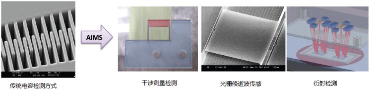
Figure 8 Optical MEMS gyroscope developed by AIMS
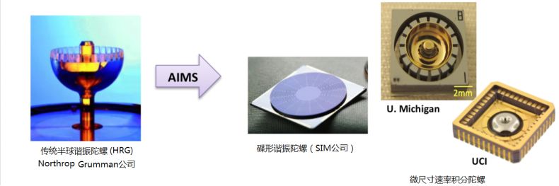
Figure 9 Rate integration gyro developed by the AIMS program
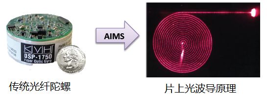
Figure 10 The on-chip optical waveguide gyroscope developed by AIMS
2 future high-end MEMS gyro key technology
MEMS gyro will continue to break through and introduce many key technologies, gradually improve the accuracy, and can be used more and more widely in the future high-end applications.
Electrostatic balance adjustment technology
MEMS process errors are always inevitable, and high-precision MEMS gyros are very sensitive to process errors. The process error will make the device stiffness and damping asymmetrical, the driving mode and the sensitive mode have frequency difference, the gyro sensitivity is reduced, and the precision is greatly reduced. Process errors are random, so getting high-precision MEMS gyros is often a "one hundred pick one." Correcting and adjusting the process error makes the high-precision MEMS gyro change from “one hundred one pick one†to “one hundred onesâ€, which is an important technical way to ensure the high precision gyro yield. Electrostatic balance adjustment technology is a high-efficiency, low-cost process error adjustment technology. The electrostatic balance adjustment can adjust the stiffness symmetry through the electrostatic negative stiffness effect, so that the driving mode and the sensitive modal frequency tend to be consistent to improve the accuracy. Electrostatic balance adjustment technology involves the basic theory of electrostatic balance, electrostatic balance electrode arrangement, adjustment voltage criterion and test, electrostatic voltage application method, electrostatic regulation automation, etc., which are important key technologies for high-end MEMS gyro in the future.
Rate integral control technique
Rate integral gyro, also known as full-angle mode gyro. The rate-integrated gyro has many advantages over the rate gyro: the rate-integrated gyro has a larger dynamic range, no bandwidth limitation, and the noise error does not accumulate over time. Therefore, the rate integral gyro is one of the important development directions of high-precision gyro in the future. Rate integral control technology is the key technology to achieve rate integral gyro.
Atomic clock frequency locking technology
The atomic-level frequency-locked MEMS gyro is a MEMS gyro based on atomic-level frequency-locking technology to improve accuracy. The atomic-level frequency-locking technique applied to MEMS gyros is designed to synchronize the MEMS gyro resonant frequency with an extremely accurate frequency reference (atomic clock level accuracy), using the "atomic clock level" frequency accuracy to lock the MEMS gyro resonant frequency Constant value, independent of environmental influences. The atomic-level frequency-locking technology can increase the angular random walk and zero-bias stability of the MEMS resonant gyro by several orders of magnitude, thus making the gyro accuracy have a leap-forward improvement. Atomic-level frequency-locking technology is a technology that greatly increases the accuracy of MEMS gyro.
System self-calibration technology
Self-calibration technology refers to the technology of automatically calibrating and zeroing the zero output after the sensor is powered on. Through the self-calibration technology, the gyro zero-offset output is cancelled, and the problem of inconsistent zero-bias of the gyro multiple times is eliminated, which plays an important role in improving the zero-repetition repeatability, especially the accuracy of long-term angle detection. Self-calibration technology is another technical bottleneck to ensure the accuracy of MEMS inertial sensors.
Light detection technology
The optical detection method has the advantages of simple structure, high precision, good stability, anti-electromagnetic interference, etc. The combination of optical detection and MEMS sensor makes the measurement precision higher and the measurement more intelligent, and has broad market prospects.
High Q technology
High Q value is an important way to improve the sensitivity of gyro, and it is one of the key technologies of high precision MEMS gyro in the future.
04
Summary and inspiration
In summary, HRG is a typical solid wave gyro with high precision and has been widely used. However, HRG processing is difficult and the batch production capacity is poor, so MEMS resonant ring gyro and resonant disk gyro suitable for planar processing are gradually derived. The MEMS planar gyro with full symmetry has good environmental adaptability. The MEMS gyro of many military enterprises in the United States and Europe adopts MEMS planar gyro design and processing technology with full symmetry characteristics, and is obtained on missiles, artillery shells, satellites and space vehicles. Widely used, it is the direction of the development of high-end MEMS gyro in the future.
Torque Sensor,Torque Transducer,Rotary Torque Sensor,Torsion Sensor
GALOCE (XI'AN) M&C TECHNOLOGY CO., LTD. , https://www.galoce-meas.com