This paper mainly analyzes several common interface circuit forms of plc digital input module (DI module) and sensor instrument. For the different structure of DI module internal input circuit and sensor output interface electric part, the wiring when connecting with each other is given. The method ensures the correctness of instrument selection and on-site construction wiring in future engineering design.
1 Introduction In engineering design and on-site construction, various types of instrument wiring problems are often encountered. Only by fully understanding the internal wiring mode of the instrument sensor and the internal circuit structure of the PLC, can the correct selection and ensure the selected instrument Correct wiring with the manufacturer's PLC. Therefore, it is necessary to have a clear and systematic understanding of the input and output circuits inside the PLC I/O module and the common instrument output interface.
In order to prevent the interference caused by external lines from causing abnormal operation of the PLC and even causing damage to the internal components of the PLC, the input interface circuit of the PLC digital input module (referred to as the DI module) often uses the photoelectric coupling element to isolate the input signal from the internal circuit. The connection between. The signal at the input drives the internal light-emitting diode of the optocoupler. The LED emits light and the phototransistor is turned on to reliably transmit the external input signal to the processor.
The interface circuit of the common terminal of PLC DI module of each manufacturer has the common point of the positive coupler and the negative pole of the optocoupler, and the output circuit of various instruments has dry contact, active output, high level and low level output. Therefore, when selecting an external instrument sensor, we need to distinguish and understand the output circuit of the selected PLC DI module and the structure of the sensor instrument output circuit in order to correctly select the type to ensure the construction of the PLC at the later stage. Correct wiring of the DI module.
2 PLC DI modules are classified by input type
The input interface circuit of the PLC DI module can be divided into DC and AC input circuits according to the external power supply category; according to the flow direction of the input common terminal current, it can be divided into source input and drain input circuits; according to the connection mode of the common end of the optocoupler LED Can be divided into common anode and common cathode input circuit.
3 Classified by type of external power supply
3.1 DC input circuit
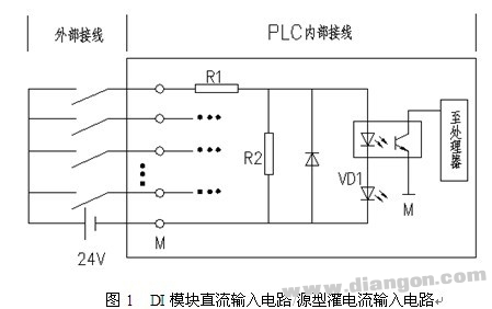
Figure 1 shows the DC input circuit (only one input circuit is drawn). The input voltage of the DC input circuit is generally DC24V. The DC input circuit requires the external input signal to be a passive dry contact (DC power supply is provided by the PLC cabinet) or a DC active contactless switch contact. When the external input contact signal is closed, the input terminal is connected to the DC power supply positive. The current passes through the resistor R1, the internal LED of the optocoupler, VD1 (interface indication) forms a loop to the COM terminal; the phototransistor saturates and conducts, and the conduction signal is transmitted to the processor, so that the CPU considers that the signal has a signal input. When the external input component is disconnected from the positive pole of the DC power supply, the LED in the optocoupler is turned off, the phototransistor is turned off, and the CPU considers that there is no signal input on the path. The DC power supply can be provided internally by the PLC cabinet or by an external DC power supply.
3.2 AC input circuit
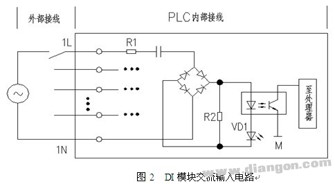
As shown in Figure 2, the AC input circuit has an input voltage of 120V or 230V at the AC input. The circuit requires the contact of the external input signal to be a passive dry contact signal or an AC active contactless switch contact signal. It differs from the DC input circuit in that a step-down circuit and a rectifier bridge circuit are added in front of the photocoupler. The AC current is limited by the current limit of the resistor R and the capacitor C (filtering out the DC part of the power supply), and then through the bridge rectification, becomes the DC current after the step-down, and the subsequent circuit principle is consistent with the DC input circuit. As can be seen from the figure, since the current limiting circuit adds three stages of current limiting, isolation and rectification, the delay time of the input signal is longer than that of the DC input circuit, which is a disadvantage. However, because its input is high voltage, its input signal is more reliable than the DC input circuit. The AC input circuit is generally used in harsh environments such as oil mist, dust, etc., where the responsiveness is not high, and the DC input mode is used in a good environment, electromagnetic interference is not serious, and the response time is high.
4 Classification by flow direction of current flowing into the common terminal
Inside the PLC DI module, one end of all input circuits (photocouplers) is connected to the common terminal (COM or M), and the other end of each input circuit is connected to its corresponding input terminal, which is also called single-ended common point input. This can reduce the input terminals.
The current flows from the input terminal of the DI module and flows into the negative pole of the power supply, which is the sink current or the sink type input; the current flows from the positive pole of the power supply to the common terminal, and the positive pole of the power supply is connected to the common terminal, that is, the common anode; the sensor is low level. effective.
The current flows from the positive pole of the power supply to the input terminal of the DI module, that is, the current current or the sinking input; the current flows from the common terminal to the negative pole of the power supply, and the negative pole of the power supply is connected to the common terminal, that is, the common cathode; the sensor is active high.
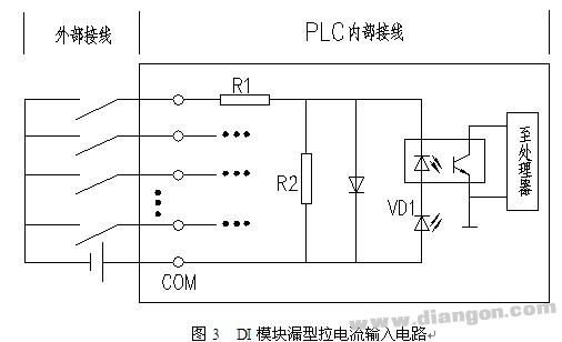
4.1 Leakage type current input circuit The leakage type current input circuit is shown in Figure 3. At this time, the current flows from the input terminal and flows into the negative pole of the DC power supply. The positive pole of the DC power supply flows into the PLC common terminal (COM terminal or M). end).
4.2 Source-type sinking current input circuit The source-type input circuit is shown in Figure 1. At this time, the current flows in the opposite direction to the drain-type circuit. The current flows from the positive pole of the DC power supply to the input of the DI module, and flows from the common terminal to the negative pole of the DC power supply.
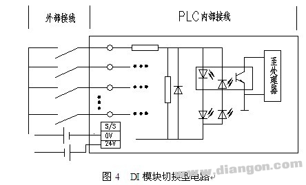
4.3 Switching input circuit In order to adapt to the usage habits of various regions, the internal common terminal of PLC DI module of some manufacturers adopts S/S terminal, which can be connected with 24V+ (positive) or 24V- (negative) of power supply. The change of the external meter wiring makes the input circuit of the DI module either a sink type input circuit or a source type input circuit. It is more flexible than the DI module using the common terminal (COM terminal or M terminal). The development of the S/S terminal is for the industrial control occasions where the Japanese and European PLCs are used in combination, and the S/S terminal is also called the SINK/SRCE switchable type. Its circuit form is shown in Figure 4. When used as a source input, the common terminal is connected to the negative terminal of the power supply; when it is a drain input, the common terminal is connected to the positive terminal of the power supply. In this way, it can be wired according to the needs of the site, which brings great flexibility to the wiring work. By selecting, all inputs of the base unit can be set to sink input or source input, but not mixed.
The leakage type pull current input circuit, the source type sink current input circuit, and the switching type input circuit are all DC input circuits.
5 The internal circuit of the sensor switching signal and its connection with the PLC input circuit In the engineering design process, various instruments that output as a switching signal are often encountered, such as: pressure switch, flow switch, level switch, Temperature switch, valve status feedback, motor operating status, fault status, etc. The output circuits of these sensors come in a variety of styles. Therefore, they need to be fully understood to ensure matching wiring with the DI module of the selected PLC.
5.1 Passive dry contact valve and other limit switches, travel switches, motor remote / local button switches, pull switches, deviation switches, relay contacts of motor running status, etc., are passive dry contact signals, do not exist The polarity factor of the power supply is relatively simple and the wiring is easy, and can be applied to the above various types of DI input modules.
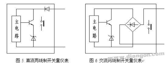
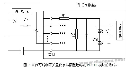
5.2 Active two-wire sensor active two-wire sensor (such as proximity switch, etc.), divided into DC and AC, DC two-wire switch Diode diode polarity protection Figure 5 and bridge rectification polarity protection Figure 6, the former is connected The PLC needs to pay attention to the polarity, and the latter does not need to pay attention to the polarity.
The wiring of the DC two-wire switch meter and the leakage current PLC DI module is shown in Figure 7:
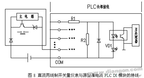
The wiring of the DC two-wire switch meter and the source sink current PLC DI module is shown in Figure 8:
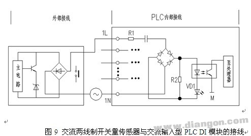
The wiring of the AC two-wire switch meter and the source sink current PLC is shown in Figure 9:
5.3 The output signal of the active three-wire sensor sensor, in addition to some dry contact signals such as the stroke switch and the relay contact, some sensors also provide NPN and PNP open collector output signals. The essence is to use the saturation and cutoff of the triode, output two states, that is, high level and low level signals, belonging to the switch type sensor. The output signals of PNP and NPN sensors are the opposite. For PLC DI module input circuits of different manufacturers, whether NPN or PNP type output sensors are used, sometimes they feel at a loss. The following mainly introduces the wiring of the two output type sensors and the PLC DI module input circuit.
5.3.1 Forms of NPN and PNP output circuits

Figure 10 shows the NPN sensor output circuit: the output of the NPN open collector output circuit (OUT terminal) is connected to the negative pole of the DC power supply through a three-stage tube. In the initial state, when the sensor is not operating, the triode is in the off state, the output terminal (OUT terminal) is close to the positive pole of the direct current, which is high level; when the sensor is operated, the triode is saturated and the current at the OUT terminal flows to the negative pole of the DC power supply, and the output is low. The level signal, the OUT (output) potential is close to the negative pole, that is, the high level is usually said to be turned low.
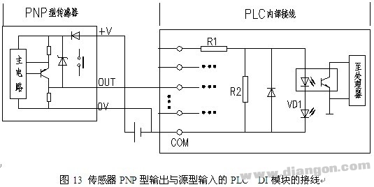
Figure 11 shows the PNP-type sensor output circuit: the output (OUT) of the PNP open-collector output circuit is connected to the positive terminal of the DC power supply through a triode. When the sensor is activated, the triode is saturated and turned on, the positive current of the DC power supply flows to the OUT terminal, and the potential of the OUT terminal (output terminal) is close to the positive pole of the DC power supply, and the high level signal is output, that is, the low level is generally said to be turned to a high level.
5.3.2 Connection of NPN and PNP output circuits and PLC input modules
1) Open circuit output of NPN collector It can be seen from the above analysis that the output of the NPN collector is 0V when it is turned on. When the output OUT terminal is connected to the input of the PLC DI module, the current flows from the input end of the PLC and flows in from the common end of the DI module. The input circuit of the PLC DI module is a sink type input circuit, that is, the sensor of the NPN type output can only be connected to the DI module of the leakage type or switching type input circuit, as shown in FIG.

2) PNP open collector output
When the PNP collector is turned on, the output is +V high. When the output OUT is connected to the PLC DI module input, the current flows from the input of the DI module and flows out from the common terminal of the DI module. The input circuit of the PLC DI module is The source input circuit, that is, the PNP output sensor can only be connected to the DI module of the source or switching input circuit, as shown in Figure 13:
6 Conclusion Because of the diversity of sensor output signals and PLC DI module input circuit form, we must fully understand the type of PLC DI module input circuit and the form of sensor output signal in the process of engineering design. Only in this way can we ensure After the PLC manufacturer determines the correctness of the instrument sensor selection, it can ensure that the correct connection between the sensor and the PLC input module without adding additional components can be used in practical applications.
With the development of the times, the consumption level of people is gradually increasing. At the same time, people's entertainment methods are beginning to diversify, especially for modern young people. As a result, different kinds of electronic products are starting to be in people's lives, and the booming Electronic Cigarette industry reflects this.
Described including the upper shell, the upper shell at the top of the smoke outlet, as described in the bottom of the upper shell with airway, described with the smoke outlet in the airway and also to match the upper shell, the lower part of the shell described the airway in the direction of the lower shell extension, as described in the lower shell near one end of the upper shell is equipped with oil mouth, described the lower shell with batteries, described at the bottom of the bottom shell has come in The air port is provided with an oil storage bin in the lower shell, and the air passage passes through the oil storage bin and is provided with a heating atomization bin at one end away from the smoke outlet. The utility model has beneficial effects: it can meet the smoking habit of different users, avoid the premature end of the use experience caused by excessive consumption of smoke oil, and indirectly prolong the service time and life of the product.
Refillable E-Cig Oem,Refillable Vape Pod,Refillable Vape Pen Oem,Refillable Mod Oem
Shenzhen MASON VAP Technology Co., Ltd. , https://www.e-cigarettefactory.com