Abstract : Sound source localization tracking technology has been widely used in today's society. Here, two high-sensitivity microphones are used as sensors, coupled with an audio signal processing chip, receiving audio signals and performing analog-to-digital conversion, using an FPGA device as a core controller, combining TDOA algorithm and ILD algorithm to realize indoor environment and two-dimensional Sound source localization in the plane. And according to the information of the sound source positioning, the camera is rotated to keep it aligned with the sound source and keep track. The FPGA uses the Nios II core for easy programming in high-level languages. The camera's video output signal can be connected to a PC or other video device. Compared to other positioning algorithms, the system reduces the number of sensors used.
This article refers to the address: http://
In daily life, sound source tracking and positioning technology has a wide range of applications. For example, in a video conference, sound source localization is used to detect the position of the speaker, and automatically adjust the camera rotation angle to make it aimed at the speaker; in the stage performance, the sound source localization tracking may be that the camera automatically keeps pointing to the host or the main character; In the security system, the sound source localization technology allows the surveillance camera to align with the sound source at the moment the sound is generated in the surveillance area, and keep track of the moving sound source.
Nowadays, the common microphone sound source localization algorithm is more common in the TDOA algorithm. The basic principle is to estimate the distance difference between the signals reaching the microphones of two different positions according to the time difference of the signals reaching the microphones at two different positions, and a hyperbolic equation can be listed. At the same time, using another two different microphones to simultaneously detect the signal, another hyperbolic equation can be obtained. The intersection of the two hyperbolic equations is the position coordinate of the sound source. When using this method for sound source localization, at least three microphones must be used, and the TDOA algorithm is used twice to perform a positioning operation. In order to achieve more accurate sound source localization, array technology is often used to form a plurality of microphones into a line array, or a square array to acquire signals for sound source localization. But the algorithm of this positioning technology is more complicated. In this paper, two high-sensitivity microphones are used as sensors, and FPGA is selected as the controller. When the sound source is positioned, the stepper motor is controlled to rotate, so that the camera is aligned with the sound source. When the sound source position moves, the camera can be automatically tracked.
1 Design principle
The system uses the combination of TDOA algorithm and ILD algorithm to realize the localization of sound source. In a two-dimensional plane, that is, when the sound source and the microphone are in the same plane, the signal model received by the microphone can be expressed as considering the inverse square law of signal propagation:
x(t)=s(t-Ï„)/d+n(t) (1)
Where: s(t) is the source signal; n(t) is additive white noise; d and Ï„ are the distance and delay of the signal arriving at the microphone, respectively.
The ILD method can be used to ignore the delay information when calculating energy. In the time range [0, l], the signal energy received by the microphone is the sum of the squares of the signal samples during that time period, namely:
For an array of two microphones, the relationship between the energy received by the microphone and the distance of the microphone from the sound source is:
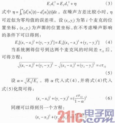
The position coordinates of the sound source can be obtained by solving the equations composed of equations (6) and (7). The closed solution of the equation can be obtained by further transformation.
2 system hardware design
This article uses Altera's Cyclone III series FPGA chip EP3C16F484 as the core processor. The UDA1341 chip is used as a processing chip for the front-end audio signal acquisition circuit, and two high-sensitivity microphones are used as sensors for the audio signal. The two microphones are oriented in the same direction with a spacing of 0.5 m. The microphone needs to be calibrated before use to ensure that the amplitude of the received signal is the same when the microphone receives the same signal at the same position. The two-phase stepper motor is used to control the angle of rotation of the camera. In order to record data, a 4 Mb FLASH memory was added to the system, and a 16x2 liquid crystal with a font library was used to display the positioning information. In order to ensure that the camera's line of sight is not disturbed by environmental obstacles, the camera should have a certain height when placed, generally higher than the height of the microphone. Therefore, two stepping motors are needed to adjust the angle of the camera, one to adjust the horizontal rotation angle, and the other One adjusts the pitch angle. The system block diagram is shown in Figure 1.
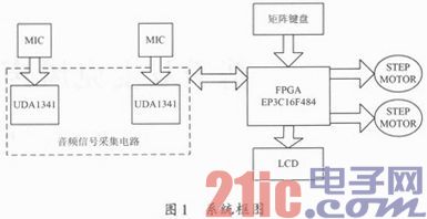
The EP3C16F484 is a Cyclone III FPGA that is a low-cost FPGA device for the end market. It has 15 408 logic cells, 56 embedded multipliers, 4 phase-locked loops, and 346 user-defined I/O pins. . Can meet the application of the general system core controller. UDA1341 is an economical audio signal acquisition and coding chip. It has two ADC modules with an oversampling ratio of up to 128. It can be programmed to set various operating parameters such as gain. The system first performs initialization operation at startup, and sets the working mode and working parameters of the chip through the L3 bus interface of the UDA11341 chip. The audio signals received by the two microphones are processed by the audio signal acquisition circuit, converted into discrete signals, and sent to the FPGA for processing. The controller determines the time difference of the signals received by the two microphones and the attenuation of the signal power according to the sequence of the received signals, thereby calculating the position coordinates of the sound source. Control the rotation of the stepper motor to align the camera with the sound source. The system simultaneously displays the measured position coordinates of the sound source on the LCD. The user can establish a positioning coordinate system according to the specific use environment when using. After determining the coordinate system, the position of the two microphones and the coordinates of the position of the camera are input into the system through the matrix keyboard at the time of system startup initialization.
3 system software design
The languages ​​commonly used in FPGA programming are the VHDL and Verilog HDL languages. Both languages ​​are hardware programming languages, powerful, can be used to describe the structure, functions, etc. of digital systems, and are very logical, but if used for programming some signal processing algorithms, the difficulty and workload are relatively large. Altera has introduced the Nios II core that can be ported to an FPGA chip. The kernel can be used to easily cut system resources, and the program development using C/C++ language greatly reduces the difficulty of using FPGA development. In order to ensure the real-time response of the system, this article uses the NIOSII/f core. Although it occupies a large amount of FPGA resources, it achieves the highest system performance. Other system resources added at the same time include: on-chip SRAM 63 KB, a timer, a serial port, a JTAG interface, a FLASH controller CFI, a 5-bit general-purpose I/O port for the matrix keyboard, for liquid crystal display. 16-bit general purpose I/O port, two 9-bit general purpose I/O ports for the input of the front-end data acquisition circuit, and two 1-bit I/O ports for controlling two stepper motors. After the configuration and compilation of the Nios II kernel is completed in the Quarters II 9.0 development environment, the program is written in the C++ language in Nios IIIDE. Figure 2 shows the software flow chart.
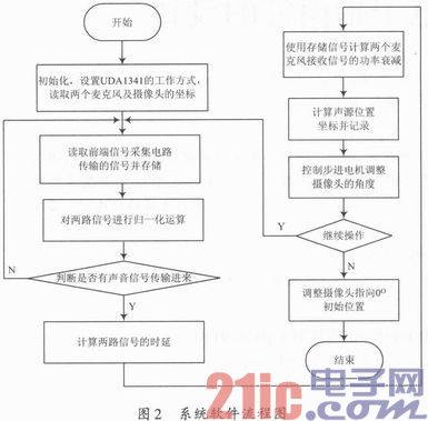
After the system is started, the initialization operation is first performed, the working mode of the UDA1341 is set, and the position coordinates of the microphone and the camera are set. The audio signal emitted by the sound source is processed into a discrete time signal after being processed by the front end signal acquisition circuit. Each time the system reads the same length sequence of the same time period from the two outputs of the front-end signal processing circuit, it stores it in the memory until the next time the data is read and updated. The system normalizes the read audio data to eliminate the difference in energy received by the two microphones. Then, a generalized cross-correlation operation is performed on the two columns of signals to determine whether there is an effective input of the sound source signal. If there is an effective sound source signal input, the time difference between the signals received by the two microphones is calculated according to the sampling rate of the front end signal acquisition circuit. And using the stored original signal to calculate the power attenuation of the signals received by the two microphones, according to equations (6), (7), calculate the position coordinates of the sound source, and store.
If there is no valid signal input, the system continues to read data from the front-end processing circuit and continues to judge. When the system is installed, in order to prevent the camera's line of sight from being obstructed by obstacles, the camera should be installed at a higher position than the two microphones. Therefore, when calculating the rotation angle of the camera, it is necessary to consider the horizontal rotation angle of the camera, and also consider the rotation angle of the camera in the vertical direction. After calculating the position coordinates of the sound source, the system calculates the angles that the camera needs to rotate in the horizontal direction and the vertical direction according to the direction of the current camera, and controls the stepping motor to rotate so that the camera points to the position of the sound source. After completing a positioning operation, the system continues to read data from the front-end circuit for the next positioning operation.
4 experimental test
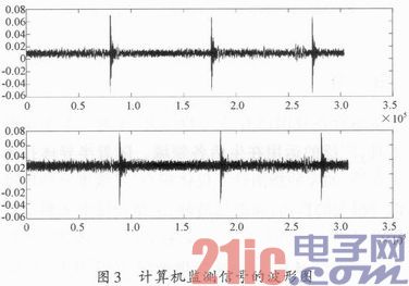
Since only two microphones are used in the design, the positioning and tracking of the 180° range of the front of the microphone can only be realized in a two-dimensional plane. The height of the camera should be higher than the height of the sound source. Otherwise, the camera may not be visible. The location of the sound source. Tested in an indoor environment of 10.8 m × 7.5 m × 3.5 m, the microphone and camera are placed at the boundary, the microphone is placed at a height of 1.5 m, and the sound source is at the same height, and the camera is placed at a height of 2.0 m, in order to ensure that the solution of the equation can be obtained. The coordinates of the microphone cannot be set on the coordinate axis; the coordinates of the microphone 1 are (1.0, 1.0), and the coordinates of the microphone 2 are (1.5, 1.0). Using the pulse signal generated by the signal generator as the sound source, each group of signals has only one pulse, the frequency is 2 kHz, the amplitude is 3 V, and each group of pulses is transmitted at intervals of 2 s. The sound is played through a speaker, and the indoor environment is kept quiet. By moving the sound source indoors at a slower pace, the system can track the sound source normally, so that the camera keeps the sound source within the field of view of the lens. Figure 3 is a waveform diagram of an audio signal monitored by a computer. The upper waveform is the signal received by the microphone on the right side, and the lower waveform is the signal received by the microphone on the left side, where the microphone on the right is closer to the sound source. It can be seen from the waveform diagram that the signal received by the microphone on the left side has a certain delay relative to the microphone on the right side, and the amplitude of the received signal is also smaller. The system is designed to use only two microphones as sensors. When the sound source moves to the mid-perpendicular position of the two microphone connections, the equation cannot be solved because the energy attenuation of the signals received by the two microphones is the same. The position of the microphone can be further deflected by slightly deflecting the angle so that the sound source deviates from the center line.
5 Conclusion
In stage and video conferencing, sound source location tracking technology has many advantages over other technologies. Sound source positioning tracking can realize fully automatic working mode, and no manual control is required during the working process. Compared with the infrared tracking and positioning system with the same function, the tracking target does not need to carry the infrared emitting device, and does not have to consider the angle and frequency of the infrared emission. Compared with the method of image tracking, the system structure and algorithm are simpler. At the same time, if the camera is replaced by a spotlight, the automatic tracking control of the lamp can also be realized. In the existing design, if a point of a two-dimensional plane is to be determined, at least three microphones are required as signals to receive signals. This design uses two microphones as system sensors, using the combination of TDOA algorithm and ILD algorithm to achieve positioning operation. A microphone is reduced compared to the existing design, making the system smaller, while also reducing the need for microphone placement, allowing the microphone to be more flexible depending on the specific environment.
Submersible Uv Sterilizer,Aquael Uv Sterilizer,Filter Uv Aquarium,Uv Sterilizer Pets At Home
JIANGMEN LEDERLIGHT LIGHTING Co.,LTD , https://www.lederlightcn.com