0 Preface
The residual current action protector is an important protection device in the low-voltage power grid. The real-time status monitoring of the residual current action protector in the intelligent transformation of the agricultural network can greatly improve work efficiency and save labor cost. Aiming at the large and scattered distribution area of ​​agricultural network equipment, this paper proposes a design scheme of remote monitoring system for residual current action protector based on GSM.
The residual current action protector remote monitoring system (referred to as the detection system) is composed of a front end residual current action protector, a single chip control system, a GSM short message transceiver module, a monitoring computer and a mobile terminal. A single-chip microcomputer control system simultaneously connects multiple residual current action protectors for data communication and transmission control.
The MCU for monitoring system control selects the MC68HC90JL8 product of a certain company, detects the state of the connected residual current action protector and completes the related data communication. The device status data is transmitted by SMS, through the GSM transceiver module to the mobile terminal or monitoring computer.
The short message transceiver module selects a company's G100 model product, integrates the key GSM module TC35i and the module's RF processing circuit, SIM card slot and MCU microprocessor unit, and realizes transparent data transmission by RS232 communication protocol.
1 How the monitoring system works
As the front end of the system, the residual current action protector is installed in each low-voltage grid control box to automatically monitor the status data of the power line (including load voltage / load current / leakage current, etc.). When an overload, short circuit, phase loss, over voltage, under voltage or residual current fault trip occurs on the power line, the residual current action protector sends a text message to the mobile terminal or monitoring computer through the core MCU control system and the GSM SMS transceiver module. The main contents include status data such as alarm location, alarm line, alarm cause, and alarm value. Managers can grasp the fault information in time and take prompt measures to ensure normal power supply.
During the whole system working process, the MCU control system not only monitors the protector status data in real time, but also automatically sends the alarm information to the management platform and the mobile terminal when the status and data of the power line changes. At the same time, the MCU control system can also receive the instructions of the management personnel to perform corresponding operations.
When the control system receives the instruction in the form of short message, the status information and data parameters of the residual current action protector can also be collected in real time and transmitted back to the monitoring platform and the mobile terminal for analysis and statistics by the management personnel.
On the management platform, the monitoring computer collects the state information and data parameters of the residual current action protector of each power line, and performs statistical analysis on the operation based on the existing comparison data, and can be in the form of an output report. Management decisions provide effective reference information.
2 monitoring system hardware design
The monitoring system adopts the functional modular design with comparative advantages, which can be divided into single-chip control system and communication module design. The design of the single-chip control system and communication part includes hardware circuit design and software design.
The control system and communication module are mainly composed of core MCU, power processing circuit, keyboard input circuit, signal processing circuit, liquid crystal display circuit, GSM transceiver module, etc., as shown in Figure 1.
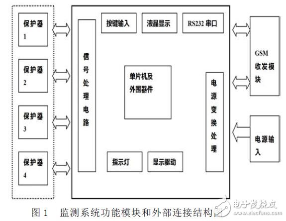
According to the field research and analysis, in general, the residual current action protectors connected to the same low-voltage power transformer are basically laid out in the same power distribution cabinet, the number of installed protectors is relatively small, and the distance between the installations is relatively close. It is the installation feature of the residual current action protector in the low-voltage network. According to its characteristics, the connection between the residual current action protector and the MCU control system in this system adopts the TTL level direct mode, and at the same time, each MCU control system can be connected to control 4 residual current action protectors.
The power supply of the MCU control system and the GSM transceiver module is mainly supplied by the AC220V input after being transformed, rectified and filtered. The number of the residual current action protector is determined by the communication interface code of the MCU control system; the key input part adopts 4*4 The method of row and column scanning query realizes the input of numbers and corresponding character commands; the display unit part adopts dot matrix display liquid crystal, which can display the Chinese information corresponding to the key input, and also displays the corresponding alarms in the state of sending and receiving short messages, transceiver module initialization and work malfunction. information.
3 monitoring system software design
3.1 Main functions of the system
The monitoring system mainly implements the following functions:
(1) realizing state data acquisition of the residual current action protector controlled;
(2) Realizing two-way communication between transceiver modules according to the specified format;
(3) realizing analysis, processing, and encoding of the state data of the residual current action protector, and generating a data frame, and then transmitting the data to the monitoring computer and the mobile terminal through the GSM module;
(4) Realizing decoding, analysis and processing of the received short message, and applying a control command to the residual current action protector to complete the corresponding action;
(5) In addition, it is flexible to use the button to set or change the mobile phone number to be sent, and display relevant information on the liquid crystal unit;
(6) Display various faults of the residual current operated protector on the liquid crystal cell.
3.2 Main function module design
3.2.1 Data acquisition module design
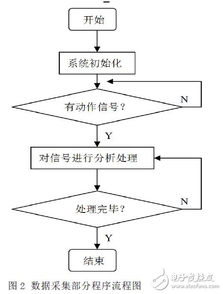
The data acquisition module of the single chip computer collects the state data of the connected residual current action protectors in real time. The residual current action protector itself has corresponding protection actions when there are undervoltage, overvoltage, short circuit, excessive leakage current and other faults on the line. Now, the MCU needs to collect such fault information in real time and make Corresponding identification and processing to determine the specific line and specific fault type in which the fault occurred. The fault information is integrated in the later stage, and the line fault alarm information is prepared. The fault information content generally includes the location where the fault occurred, the line and the specific time. Figure 2 shows the flow chart of the data acquisition module program.
Big Water Tank Robot Vacuum Cleaners
Big Water Tank Robot Vacuum Cleaners,Ultrasonic Cleaner Water Tank,Robot Vacuum Cleaner,Virtual Blocker
NingBo CaiNiao Intelligent Technology Co., LTD , https://www.intelligentnewbot.com