0 Preface
The voltage type PWM means that the controller adjusts the output pulse width according to the feedback voltage, and the current type PWM means that the controller adjusts the output pulse width according to the feedback current. The current-mode PWM is used at the input of the pulse width comparator to directly compare the signal flowing through the output inductor current with the error amplifier output signal to adjust the duty cycle so that the peak current of the output changes following the error voltage. Because of the voltage loop and current loop double loop system, the voltage regulation rate, load regulation rate and transient response characteristics of the switching power supply are improved. It is an ideal new PWM controller.
1 Double-loop current type PWM controller works
The dual-loop 24V power supply current-mode pulse width modulation (PWM) controller adds control of the current feedback inside the common voltage feedback PWM control loop. In addition to the function of the voltage-type PWM controller, it can also detect the switching current or inductor current. , realize double loop control of voltage and current. The circuit principle of the dual-ring current type PWM controller is shown in Figure 1.
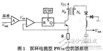
As can be seen from Figure 1, the 24V supply current type controller has two control closed loops: one is the output voltage feedback error amplifier A, which is used to generate the error voltage after comparison with the reference voltage; the other is the transformer primary (inductor) The voltage generated by the current on Rs is compared with the error voltage to produce a pulse width of the modulated pulse such that the error signal actually controls the peak inductor current.
The system works as follows: Assume that the input voltage drops, the rectified DC voltage drops, the output voltage drops due to the inductance delay, the error is delayed by the error amplifier, the Vea rises, the duty cycle changes, so that the output voltage remains unchanged, and the inductance in the current loop The peak current also decreases with the input voltage, and the slope of the inductor current di/dt decreases, causing the ramp voltage to delay reaching Vea, increasing the PWM duty cycle and adjusting the output voltage. Since the voltage and the current are controlled, the control effect is well used in practice.
2 characteristics of double loop current type PWM controller
a) Since the change of the input voltage Vi is immediately reflected as the change of the inductor current, the output pulse width (current control loop) can be changed in the comparator without the error amplifier, so that the voltage adjustment rate of the system is very good, and can reach 0.01%. /V, compared to linear shifters.
b) Due to the inherent fast response and high stability of the 24V power supply dual-loop control system, the gain of the feedback loop is high, which will not cause the contradiction between stability and gain, and the output voltage has high precision.
c) Since the peak inductor current is induced on Rs, as long as the level on Rs reaches 1 V, the PWM controller is immediately turned off, forming a pulse-by-pulse current limiting circuit, so that the power switch tube is in any input voltage and load transients. The peak current is controlled within a certain range to effectively protect the main switch during overload and short circuit.
d) The error amplifier is used to control the change of the output voltage due to the load change, so that the amplitude of the voltage rise is greatly reduced when the load is reduced, and the load adjustment rate is significantly improved.
e) Since the inner loop of the system is a good controlled current amplifier, the parallel current sharing can be realized by comparing the voltage signal converted into the current sampling signal with the output signal of a common voltage error amplifier, so that the system is connected in parallel achieve.
3 double loop current type PWM controller power factor correction
Based on the above characteristics, current-mode PWM controllers are more and more widely used in practical applications. It adopts power factor correction technology, which can effectively reduce the interference of high-order harmonics to the power grid and reduce power consumption, which has great practical significance.
3.1 Power factor correction method
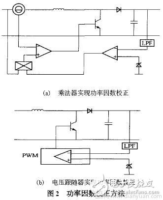
There are two main methods for power factor correction: one is to connect a common power converter on the common load side of the power grid to compensate for reactive power and harmonics; the other is to connect the load rectifier circuit and the filter capacitor. A power conversion circuit is added to correct the input current to a sine wave that is close to the grid voltage. Power factor correction can be implemented in CCM and DCM using multipliers and voltage followers. The block diagram is shown in Figure 2.
3.2 Current mode PWM controller power factor correction method
Since the multiplier is expensive, the addition circuit is used to implement the function of the multiplier. In order to make the envelope of the inductor current sinusoidal, the input voltage of the inverting input of the current sense comparator must be a sinusoidal head wave. The basic circuit is shown in Figure 3.
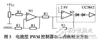
When the negative terminal of N1 is electrically rectified and sampled to obtain a sinusoidal head wave, it is applied to the sinusoidal head wave of the 1/3 of the negative side of the current sensing comparator via the diode step-down and resistor divider, so that the envelope of the inductor current is obtained. Sinusoidal. Of course, in actual use, closed-loop control is required to obtain a stable output voltage.
3 current type PWM controller slope compensation method
3.1 Peak current and average output inductor current
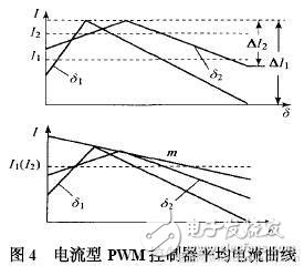
Since the peak current of the 24V power switch is kept constant by the PWM controller, that is, the peak current of the inductor is also kept constant, but the DC output voltage is proportional to the average value of the output current instead of the peak current. When the input voltage is reduced, In order to keep the current constant, the duty cycle will be adjusted to δ2, at which time the average current will rise to I2 and the output voltage will also rise. This problem will not occur in voltage-type controllers, but in voltage-type control devices, only the output voltage is controlled. Therefore, in order to solve the above problem, slope compensation is needed in the current type controller. In order to maintain a constant average current (output voltage), a duty-free current waveform compensation ramp is required. When (Ns/Np) Rs ( m2/2) = m is established, the average output inductor current is independent of Ton. , keeps the output voltage constant. As shown in Figure 4.
3.2 Implementation of slope compensation
Slope compensation can be achieved with the circuit shown in Figure 5. Generally, the resistance of R1 is preset, and then the resistance of R2 is calculated. It is important that the resistance of R2 should be high enough to avoid oscillation drift of the oscillator.
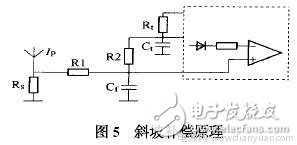
From the ramp termination resistor R2 to the current sense terminal, the slope of the induced voltage ramp on Rs is compared to the smoothed error voltage, which is very effective when the duty cycle is above 50%. The general calculation steps for R2 resistance are as follows:
a) Calculate the slope of the secondary inductor: S1 = di/dt (in A/μs);
b) Calculate the slope of the primary inductance: S2 = S1 Ns/Np (in A/μs);
c) Calculate the ramp voltage across the sense resistor: V1 = S2 Rs (in V/μs);
d) Calculate the oscillator ramp voltage on the timing capacitor CT: S = dVosc/Ton (in V/μs);
e) If the slope compensation amount M = 0.75 and the resistance value R1 of R1 is set to 1 kΩ, then R2 = R1 (Vs/VS2) M.
4 Conclusion
With the 24V power supply current type PWM controller being more and more widely used, correct use of the method can save a lot of design time and achieve better design effects, so it is a problem that must be paid attention to when using this type of controller. In this paper, the voltage-type pulse width modulator (PWM) controller has only the inherent disadvantages of voltage control loop, current variation hysteresis voltage change, slow system response speed and poor stability. A dual-loop current-type PWM controller based on 24V power supply is proposed. Design plan. Since the scheme controls both voltage and current, the control effect is well used in practice.
Dog Fence Wire,Invisible Fence Wire,Electric Dog Fence Wire,Invisible Dog Fence Wire
Elite-tek Electronics Ltd , https://www.aetertek.ca