Sine wave oscillation circuit diagrams are essential in understanding how electronic devices generate stable and precise signals. The first diagram shows a basic sine wave oscillator, which is commonly used in various applications such as signal generation and communication systems. 
The second image illustrates an RC sine wave circuit, which is a simple yet effective way to produce low-frequency sine waves. 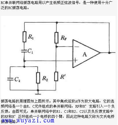
This type of circuit is widely used in audio equipment and test instruments due to its ease of implementation and cost-effectiveness.
One of the most common types of RC sine wave oscillation circuits is the RC series-parallel configuration, also known as the Wien bridge oscillator. 
In this design, the series-parallel network acts as both a frequency-selective filter and a feedback mechanism. The circuit diagram is shown in Figure (1).
For the circuit to start oscillating, the gain must be sufficient to overcome losses in the system. The starting condition can be expressed as: 
The oscillation frequency of the RC sine wave circuit is determined by the values of the resistors and capacitors in the network. It can be calculated using the formula: 
This type of circuit is typically used for low-frequency applications. However, if a higher frequency sine wave is required, an LC sine wave oscillator is often preferred. The oscillation frequency of an LC circuit is given by: 
Another important type of oscillator is the quartz oscillator. Unlike RC or LC oscillators, quartz oscillators use a piezoelectric crystal to maintain a very stable frequency. This makes them ideal for applications where high precision and stability are critical, such as in clocks, microcontrollers, and communication systems. The quartz oscillator 3225 20M OSC mentioned earlier is a typical example of this technology, offering excellent frequency stability and reliability.
Linux Pc For Iot,Iot Industrial Computer,Iot Industrial Pc,Linux Industrial Pc
Shenzhen Innovative Cloud Computer Co., Ltd. , https://www.xcypc.com