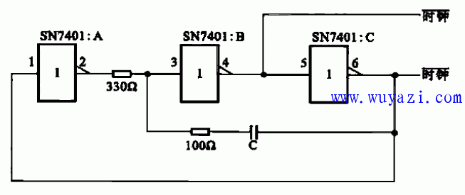
The image above illustrates an RC clock signal generation circuit commonly used in TTL systems. This design is efficient, requiring only three inverters from a 6-inverter IC like the SN7401. The clock frequency is determined by the RC time constant. For instance, with a capacitance of 200 pF, the frequency can reach up to 5 MHz, while increasing the capacitance to 1,600 pF reduces the frequency to around 1 MHz. This flexibility makes it ideal for various digital applications where adjustable timing is necessary.
2.0mm Pitch
2.0mm Pitch
HuiZhou Antenk Electronics Co., LTD , https://www.atkconn.com