The variable frequency motor mainly relies on the electronic circuit composed of semiconductor components to drive the motor to operate. Among them, the MCU digital control technology is good for the motor efficiency; while the MCU control technology is becoming more and more mature, coupled with the FOC algorithm, the inverter motor Efficiency will gradually leap forward.
The motor is an indispensable power component in home appliances, and the amount of motor used is also one of the indicators of comfort. In home appliances, there are basically three types of motors: AC InducTIon Motor (ACIM), Brushed DC Motor, and DC Brushless Motor (BLDC/PMSM) (also known as variable frequency motors). In fact, the classification of motors can be distinguished from the following points.
. power supply
From the point of view of the use of the power supply, it can be easily divided into two major categories: AC motor and DC motor.
. control method
From the point of view of motor control, it can be easily divided into two categories: synchronous control and asynchronous control (inductive control). The BLDC/PMSM motor uses a synchronous control method that uses the current control on the stator to synchronously control the rotation of the motor rotor. The ACIM motor adopts the induction control mode, which uses the control of the current loop of the stator to induce the rotor, and the rotor magnetic field ring and the stator magnetic field ring have a speed difference.
. Number of stator winding groups
The most common ones are three-phase motors and single-phase motors, in which the three-phase windings are also divided into Y-junctions and star-shaped junctions.
. Brush
From the perspective of the presence or absence of brushes, it can be easily divided into two types: brush motor and brushless motor. The brush motor supplies the DC power to the windings as brushes and commutators (the brushes are fixed on the stator and the commutators are fixed on the rotor), and the brushless motor uses electronic circuits instead of brushes and commutators. .
Home appliances accelerate the introduction of high-efficiency energy-saving motor business opportunities to take off
The main reasons for driving the use of DC motors in the use of home appliances are as follows.
. energy crisis
According to the International Energy Agency (IEA), the motor is the most power-hungry application, accounting for more than 46% of global electricity consumption. It has also become the primary improvement focus of the industry in implementing energy-saving and carbon-reduction. Among them, DC motors are highly efficient. The performance is better than the traditional ACIM. The use of DC motors has gradually become a trend in power components for home appliances.
It is estimated that upgrading from IE1 to IE3 will increase power efficiency by 8%. The implementation of the Motor Minimum Energy Efficiency Standard (MEPS) policy is currently in the promulgation period. Once it enters the mandatory period, it will set off a new wave of motor replacement and stimulate motor manufacturers and semiconductor factories to accelerate the introduction of new and more efficient new products. Program.
. Power technology advancement
Three key power technologies—Lithium battery components, Switching Power Supply technology, and solar panel power technology—combined home appliances and mobile power into new safe home and leisure concept products. For example, in recent years, rechargeable fans that are popular in Japan are advertised as safe home appliances. They can use batteries when power is off, and use adapters (Adaptor) to supply power through the mains. In addition, Europeans like to travel, rechargeable fans can be carried with you, there is no mains plug in the camping, you can also have an electric fan to blow. In addition to charging with solar panels, the rechargeable fan can also be charged with DC 12 volts (V), which is quite convenient to use.
. Digital control IC technology matures
Today, the price of microcontrollers (MCUs) has fallen sharply to cater to the design needs of home appliances without increasing the price. In addition, the digital pulse width modulation (PWM) control technology is mature, and the same IC can be used to achieve square wave or sine wave control, which makes it easier for motor manufacturers and semiconductor manufacturers to control the material in the factory.
. DC motor component advantage
At the same power, DC motor power conversion efficiency is better than the traditional ACIM. In addition, in order to reduce the cost of home appliances, it is often necessary to use plastic materials, and plastic materials are very afraid of overheating, such as health juice machine, food mixer and so on. The DC motor is less prone to burn than the AC motor, which is more advantageous.
On the other hand, at the same power, the DC motor torque is also stronger than ACIM. In recent years, the design of home appliance organizations emphasizes aesthetics and has a trend of miniaturization. Therefore, DC motors are more suitable for home appliance motor products that are smaller in size but require greater torque than ACIM, such as electric screwdrivers, water pumps for drinking fountains, and medical air pumps.
. New trends in home appliances
The improvement of the quality of life at home has become a global trend. The mute appeal and stepless speed regulation of DC motors are widely used in the functional design of new home appliances, such as DC floor fans, ceiling fans, and air conditioners.
Drive high efficiency BLDC MCU key design with doorway
BLDC motor control mainly adopts synchronous control mode. More precisely, BLDC is a double feedback control mode. The direction of the stator current is controlled by the MCU, the position of the rotor is controlled next, the rotor position is fed back, and the rotor position feedback is divided into two methods: a sensor (Hall or Encoder) and a sensorless (Sensorless). In addition, the current is returned. The main purpose of the award is for overcurrent protection. The block diagram of the entire BLDC solution system is shown in Figure 1. From the figure, the key components that determine the efficiency of the motor product can be easily seen.
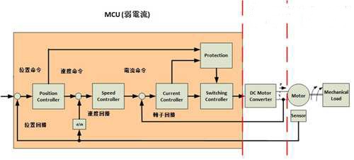
Figure 1 BLDC system configuration block diagram
. Power circuit
Mainly divided into commercial power applications and DC power applications, the main design considerations are power conversion efficiency.
. MOS component
Mainly for the Rds specification, the focus is on the heat loss of metal oxide semiconductor field effect transistors (MOSFETs).
. Gate Driver drive circuit
There are two main types - the three-level tube circuit and the gate driver (Gate Driver) IC; the focus is on the switching element loss caused by the Gate Driver Rising/Falling TIming.
. MCU
According to the product plan requirements, you can choose to use square wave or sine wave control, with motor feedback control sensor scheme and non-sensor scheme, which can be divided into four schemes: square wave Hall scheme, square wave sensorless scheme, sine wave Hall program and sine wave Sensorless program.
. Motor material
Mainly consider the power loss caused by the characteristics of the motor material such as copper loss and iron loss.
The internal design of the MCU motor control is mainly divided into five parts (Fig. 2), which are explained in the following points.
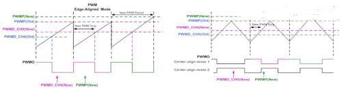
Figure 2 PWM Edge-aligned Mode and Center-aligned Mode Circuit
. PWM modulation circuit
There are two main modes: Edge-aligned Mode and Center-aligned Mode.
. Motor stator current control circuit
The square wave control and sine wave control mode is determined by the configuration of the Hall Sensor Decoder and Mask circuit.
. Motor drive circuit control
Mainly set MOS dead time (Dead-TIme), external Gate Driver circuit drive polarity, foolproof circuit and other control methods.
. Motor rotor detection circuit
Use the exclusive TImer to observe rotor position changes and detect rotor speed and stall.
. Motor protection circuit
There are two modes: motor driven over current protection circuit and motor stall protection circuit.
In addition, the motor control method basically adopts the PID control method commonly used in the control system (Fig. 3). Taking the speed loop PID control as an example, the operation steps are as follows.
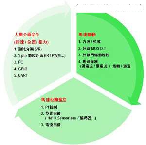
Figure 3 Motor PID Control Elements
1. Obtain the speed control command from the man-machine interface, for example, VR=0.5V represents the mechanical speed of 500rpm
2. Determine the motor stator current control mode, such as square wave control or sine wave control.
3. Monitor the rotor position of the motor and monitor the rotor speed using Hall or Sensorless.
4. The MCU calculates whether the motor reaches the speed requirement and uses the PWM mechanism to make the speed adjustment.
It is important to note that high-efficiency motor control places great emphasis on the commutation position of the commutation point and the stator current. Depending on the motor characteristics, the compensation for the commutation point may be different. It is necessary to make the commutation point according to the product requirements. The compensation and adjustment of the control makes it easy to see from the DC Bus current smoothness of the motor whether the motor control is secure.
Sterilization Card Bags
Guangzhou Ehang Electronic Co., Ltd. , https://www.ehangmobile.com