In this paper, the design of a high-reliability trolley infrared tracking circuit is proposed for the two-point deficiency of the traditional optical tracking circuit. The scheme uses low-duty-cycle strong infrared light to modulate the emission to overcome the interference of ambient light; then the AC-amplified and demodulated light-receiving signal can further overcome the environmental interference; using one-cycle transmission and reception can overcome the light diffraction to the adjacent photosensitive The interference of the tube, finally gives the circuit structure block diagram and part of the circuit diagram of the design scheme. After analyzing, the scheme avoids the cumbersome debugging workload of the traditional design and can meet various ambient light applications.
0 Preface
The previous National Undergraduate Electronic Design Competition, the National Vocational College Student Vocational Skills Competition, and the Freescale Cup National College Student Smart Car Competition almost all contain the problems of the car category. Most of the car race questions have tracked requirements. Tracking methods can be generally divided into two categories: light-controlled tracking and camera tracking. Light control tracking cost is low, software design is relatively simple, design and production cycle is short; camera control tracking is reversed: high cost, complex software design, long design cycle. The two shortcomings of the traditional light tracking circuit of the car are also obvious: one is easily affected by ambient light and is misjudged; the other is that the light diffraction phenomenon is easily received by the adjacent photosensitive tube and causes errors. Judge. In this paper, a design scheme of high-reliability trolley infrared light tracking circuit is proposed to solve this problem.
1 Traditional light tracking trolley circuit structure
1.1 Introduction to car tracking
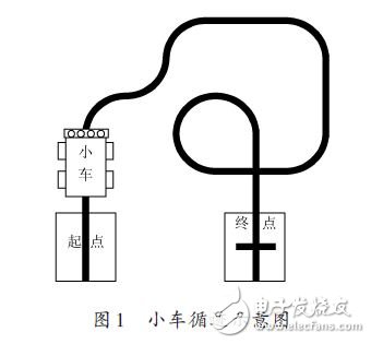
The so-called car tracking is to draw black lines on the white paper, called the track; when the car travels along the track as required (can do some specified tasks), it can automatically recognize the track and walk according to the track line. It is called a car track. As shown in Figure 1, the track is the map of the Hunan Division of the 2010 National Vocational College Student Vocational Skills Competition Lunar Rover Competition.
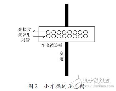
Generally, a row (or rows) of infrared light emitting and receiving arrays are installed at the bottom of the trolley to detect the track, thereby controlling the trolley to walk along the line. The light-emitting and receiving arrays are to be cross-discharged with the track, and some are also curved or inverted "V"-shaped. The more and more dense the array of infrared light emitting and receiving arrays, the more stable the control car runs, but the more complicated the algorithm is when programming. Generally, there are four or five, and more than ten, as shown in Figure 2. It is also possible to use double or even multiple rows of designs.
1.2 Traditional tracking car infrared light emission and receiving circuit
The transmitting portion of the conventional infrared light emitting and receiving circuit is driven by a direct current, and the receiving portion is a comparator. One comparison point of the comparator uses a potentiometer to adjust the DC potential, and the other compares the output of the phototube. This simple method can often meet the requirements of simple competition. However, the anti-interference ability is poor.
A traditional simple tracking circuit diagram is shown in Figure 3.
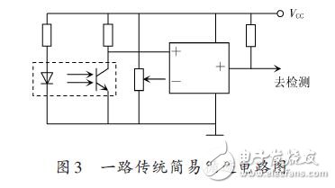
The purpose of using infrared light for transmitting and receiving is to reduce the interference of ambient light. However, if no auxiliary measures are taken, when the ambient light is strong, the interference of ambient light can not be overcome well. In addition, measures must be taken to overcome the adjacent The light is transmitted and received to interfere with the light diffraction of the tube.
2 Infrared light tracking design principles
2.1 Choosing the right light emission drive current
The emission current should generally be designed over the maximum forward current allowable value IF of the LED. After the intensity of the emitted infrared light is increased, the ratio of the infrared component of the ambient light to the total light is reduced, and a part of the ambient light interference can be overcome. However, too much increase in the emitted photocurrent will generate a large amount of heat, which will aggravate the light decay of the launch tube.
To increase the emission current while allowing the transmitter to operate safely, a low duty cycle pulse modulation emission can be used.
2.2 Pulse modulation type infrared emission and infrared receiving effect analysis
The infrared component in the ambient light shows the DC component. After the modulation [4] infrared emission measure is adopted, the modulation receiving circuit receives the modulated signal, which can filter the DC component in the ambient light.
2.3 Advantages of adopting low duty cycle pulse modulation infrared light emission
The infrared phototransistor receiving sensitivity is not lowered by the duty cycle of the infrared light emitting diode transmitting signal. After reducing the duty cycle of the infrared light emitting diode emission signal, a large current can be applied to the infrared light emitting diode, and the maximum allowable forward current IF of the infrared light emitting diode can be greatly exceeded, without damaging the infrared light emitting diode. The increased part of the current is equivalent to the intensity of the infrared light-emitting diode, and the anti-interference ability is further enhanced.
2.4 Infrared light emitted by a stable 38.5 kHz frequency modulation
The infrared modulating optical signal has the highest sensitivity in infrared light receiving at a modulation frequency of 38.5 kHz.
In order to obtain a stable 38.5 kHz modulation frequency, separate components such as resistors, capacitors, and inductors should be avoided to form a oscillating circuit with a nonlinear device to modulate the signal. A crystal oscillator or an active crystal oscillator should be used with a nonlinear component. Oscillation circuit.
Using a crystal oscillator as the external crystal of the MCU, the PWM signal with a 38.5 kHz/10%~20% duty cycle is programmed to modulate the oscillating signal. It can also be oscillated and divided by a crystal oscillator with a nonlinear device. Get 38.5 kHz/10%~20% frequency and duty cycle.
2.5 Using an AC Amplifier Circuit as an Infrared Receiver Amplifier
Even if the modulated light is flooded by ambient light, the modulated light does not disappear. After receiving the signal, it is sent to the AC amplifier for amplification. The submerged modulated optical signal can still be recovered, and the ambient light of the DC component is blocked by the AC amplifier, which effectively restores the flooded effective infrared light and overcomes the interference of strong ambient light. .
2.6 Adopting a patrol to open a certain way to transmit and receive to overcome light diffraction
The way of the crimping line should not have received the signal, and the road that is not adjacent to the pressure line continues to shine. Due to the light diffraction, the infrared light emitted from the adjacent uncompressed line is easily diffracted to the infrared receiving tube of the pressing line, resulting in a judgment error, thereby causing interference.
When the tour opens a certain way, only one way is illuminated at any time, and the detection circuit only receives the signal of this way. Even if the way of illumination is diffracted to the receiving circuit of the pressure line, the MCU does not read the diffracted way. . This overcomes the diffraction interference of adjacent channels. At this time, it is necessary to pay attention to the cycle time of collecting a tour during software design.
3 Liter Oil Deep Fryer,3L Capacity Deep Fryer,Electrical Deep Fryer,Stainless Steel Deep Fryer
Shaoxing Haoda Electrical Appliance Co.,Ltd , https://www.hotplates.nl