The ultrasonic sensor technology used in the reverse obstacle detection system can detect nearby obstacles and provide the driver with the reverse warning and auxiliary parking functions. The principle is to use ultrasonic waves to detect any obstacles present on or near the reverse path and issue them in time. caveat. The designed detection system can provide both audible and visual audible and visual warnings with warnings indicating the distance and direction of obstacles detected in the blind spot.
In this way, in a narrow place, whether parking or driving, with the reverse obstacle alarm detection system, the driver's psychological stress will be reduced, and the necessary action can be taken with ease. The PIC l8F8490 microcontroller and ultrasonic sensor are cheap and can be used on many models. Then what is the reverse sensor detection system based on ultrasonic sensors? To this end, you should first understand the technical issues related to ultrasonic sensors.
Ultrasonic sensor system configuration and working program (see Figure 1)
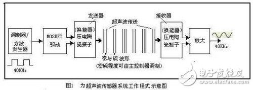
It consists of a transmitting sensor (or ultrasonic transmitter), a receiving sensor (or ultrasonic receiver), a control section and a power supply section. The transmitter sensor is composed of a transmitter and a ceramic vibrator transducer having a diameter of about 15 mm. The transducer functions to convert the electrical vibration energy of the ceramic vibrator into ultrasonic energy and radiate into the air; and the receiving sensor is transposed by the ceramic vibrator. The device is composed of an amplifying circuit, and the transducer receives the ultrasonic wave to generate mechanical vibration, converts it into electric energy, and uses it as an output of the sensor receiver to detect the transmitted ultrasonic wave. In actual use, the ceramic vibrator that transmits the sensor can also be used as the ceramic vibrator of the receiver sensor. The control part mainly controls the pulse chain frequency, duty cycle, sparse modulation and counting, and detection distance sent by the transmitter. The power source (or signal source) of the ultrasonic sensor can be DC12V±10% or 24V±10%.
When a high-frequency voltage of 40 kHz is applied to a piezoelectric ceramic piece (double crystal oscillator) having a resonant frequency of 40 kHz in the transmitting sensor, the piezoelectric ceramic piece is elongated and shortened according to the polarity of the applied high-frequency voltage, so that ultrasonic waves of 40 KHz frequency are transmitted. The ultrasonic wave propagates in a dense form (the degree of density can be modulated by the control circuit), and the ultrasonic waveform is shown in Fig. 1 and transmitted to the ultrasonic receiver. The receiver uses the principle of the piezoelectric effect, that is, applying pressure to the piezoelectric element to strain the piezoelectric element produces a 40KHz sinusoidal voltage with a "+" pole on one side and a "-" pole on the other side. Since the high frequency voltage has a small amplitude, it must be amplified.
According to the equivalent circuit and impedance characteristics of the ultrasonic sensor, it is known that the transmission sensor operates in series resonance, that is, the impedance Zr is the lowest at the resonance frequency fr, so that the maximum power can be supplied, and a large vibration sensor can be used; It works in parallel resonance, that is, the impedance Zα is the highest at the resonance frequency fα, and it is difficult to supply high power, but the impedance Zα is high to obtain a large amplitude signal, so the sensitivity of fα is used as a sensor.
The reverse operation of the ultrasonic transducer works in a reflective manner, that is, the transmitting sensor transducer transmits an ultrasonic wave of 40 KHz frequency, and after the obstacle is reached, the reflection is received by the transducer of the receiving sensor and converted into an electrical signal, see Figure 2 shows.
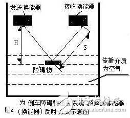
Its propagation medium is air.
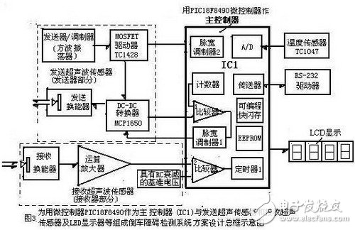
Design scheme of reversing obstacle detection system based on ultrasonic microcontroller technology
Figure 3 is a block diagram of the design scheme of the vehicle reversing obstacle detection system. The design scheme includes: IC1 main controller - using Microchip's PIC l8F8490 microcontroller as the main controller of the vehicle reversing obstacle detection system; transmitting part (ie sending ultrasonic sensor) It consists of a receiving part (ie receiving ultrasonic sensor); a temperature sensor (TC1047A), a communication interface RS-232 driver, and peripheral circuits such as an LCD or LED display.
Using a microcontroller as the master of the detection system
The microcontroller is the heart of the reversing detection system. Microchip's PIC l8F8490 microcontroller is ideal for applications such as automotive body control. Because it is a flash memory, power management microcontroller with on-chip LCD driver control module function, ie operating at 10MIPS-10 million instructions per second (MIPS), 16KB flash memory, 768 bytes RAM, with an LCD controller Two PWMs, two comparators and four timers are shown in Figure 3, intermediate IC1. It is therefore the master of the highly integrated solution for reversing ultrasonic sensor applications. The microcontroller uses nanoWatt technology to implement power management functions that significantly improve power efficiency and system reliability to meet low power design requirements including driving LCD displays in sleep mode. Its family of products offers up to 192-segment LCD drivers for a wide range of embedded control applications in a variety of package sizes and integration features.
Description of Velcro Cable Sleeve For Cable Harness
Velcro Cable Sleeve is a nonexpandable sleeving woven from monofilament (weft) and multifilament (warp) polyester yarns. It provides a lightweight, costeffective and tough solution for the protection of a wide range of components. Its inherent flexibility allows it to bend, coil and conform to irregular shapes, while its open design allows it to be installed on completed assemblies.
Material: Polyester monofilament and multifilament
Operating range: -50 °C ÷ 150 °C
Melt point: 250°C ± 5
Flammability: VW-1
Approved: RoHS, Halogen free
Standard colours : black, grey
Cutting tool: scissors
Colorful self closing braid wrap for automotive
Self closing velcro Cable Sleeve is a non-expandable sleeve woven from monofilament weft and multi-filament warp.
It provides a lightweight, cost effective and tough solution for protection of a wide range of wire and cable.
Its inherent flexibility allows it to be bend, coil and fit with irregular shapes while its open design allows it to be install on finished assemblies quickly.
Velcro Cable Sleeve
Conduit Cable Sleeves,White Fabric Cable Sleeving,Black Fabric Cable Sleeving,Velcro Cable Sleeve For Cable Harness
Shenzhen Huiyunhai Tech.Co.,Ltd , https://www.hyhbraidedsleeve.com