Squirrel cage motor auto-coupling step-start manual control circuit
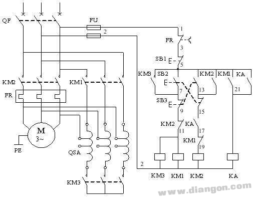
The auto-coupling step-down starting method is used to reduce the voltage applied to the motor terminals by using an autotransformer. The autotransformer typically has two sets of taps, allowing for different output voltages—commonly 80% and 65% of the supply voltage. During start-up, one of these taps (e.g., 65%) is connected to the motor circuit. Once the motor reaches near-rated speed, the autotransformer is disconnected, and the motor is directly connected to the three-phase power supply to operate at full voltage.
1. Close the air switch QF to power on the system.
2. Press the start button SB2, which energizes the AC contactor KM3 coil. The main contact closes, connecting the autotransformer in a star configuration. Then, the KM1 coil is energized, closing its main contacts and supplying power to the motor via the 65% tap of the autotransformer, enabling low-voltage startup.
3. The normally open auxiliary contact of KM1 closes, activating the intermediate relay KA. KA then self-latches, and its normally open contact prepares the circuit for KM2 coil activation.
4. When the motor approaches rated speed, release SB2 and press SB3. This de-energizes the KM1 and KM3 coils, disconnecting the autotransformer. The KM2 coil is then energized and self-latched, allowing direct power connection to the motor for normal operation.
5. Overload protection during motor operation is provided by the thermal relay FR.
6. Interlocking mechanisms are in place:
- Contactor interlock: KM2's normally closed contact is connected to the KM3 and KM1 coil circuits.
- KM1's normally closed contact is connected to the KM2 coil circuit.
- Button interlock: Pressing SB2’s normally open contact connects the KM3 and KM1 coil circuits.
- SB2’s normally closed contact connects the KM2 coil circuit.
- SB3’s normally open contact connects the KM2 coil circuit.
- SB3’s normally closed contact connects the KM3 and KM1 coil circuits.
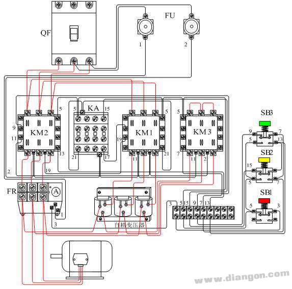
Squirrel-cage motor auto-coupling step-down start manual control circuit wiring diagram
Installation and commissioning
1. The auto-coupling step-down circuit is suitable for any three-phase squirrel cage induction motor.
2. The autotransformer’s power rating must match that of the motor. If it is too small, the motor may overheat, causing insulation damage or winding burnout due to excessive heat during startup.
3. Before testing, ensure all connections are secure and correct. Conduct a no-load test first to verify proper operation. After confirming everything works, reconnect the motor and perform a load test.
4. During the motor test, pay attention to the transition from startup to running mode. Monitor the motor’s sound and current draw. If it fails to start or shows abnormal behavior, stop immediately and check the system.
5. Frequent starting of the auto-coupling circuit is not recommended. If the first attempt fails, wait at least 4 minutes before trying again. Avoid continuous starts within 60 seconds, as this can cause excessive current in the autotransformer windings, leading to overheating and potential damage.
6. After installation, conduct a full system check. Ensure all components are functioning correctly and that the motor runs smoothly under load conditions.
Common malfunctions
1. When starting with a load, the motor produces unusual noise, runs slowly, and draws a large inrush current when switching to full voltage. Why?
Analysis: The motor struggles to start, indicating that the autotransformer tap setting may be too low, resulting in insufficient voltage for the motor to reach its rated speed. This could also be due to an overload condition exceeding the motor’s starting torque capacity.
Solution: Adjust the autotransformer tap to the 80% position and retest. This should improve the motor’s performance and reduce the inrush current.
2. When switching from start to run, the motor still experiences a large inrush current or even causes a trip. Why?
Analysis: The transition from start to full-voltage operation occurs too quickly. The motor hasn’t had enough time to reduce its starting current, leading to a sudden surge when the autotransformer is disconnected.
Solution: Increase the start-up duration to allow the motor to gradually reach near-rated speed before switching to full voltage. This helps minimize the inrush current and prevents unnecessary stress on the system.
40L Agriculture Drone Agricultural Sprayer Agricultural Spraying Drone Drones Agriculture Sprayer 30L Agriculture Drone Fertilizer Drone
Xuzhou Jitian Intelligent Equipment Co. Ltd , https://www.jitianintelligent.com