introduction
The DC-DC converter is the source of power for communication systems and has been widely used in the field of communications. Due to its high frequency, wide frequency band and high power density, it is a powerful electromagnetic interference (EMI) source. In severe cases, it will cause the surrounding electronic equipment to be dysfunctional, causing the communication system to transmit data errors, abnormal shutdowns and alarms, etc. , causing irreparable consequences; at the same time, the DC-DC converter itself is also in the surrounding electromagnetic environment, and is also sensitive to the surrounding electromagnetic interference (EMS), if it is not very resistant to electromagnetic interference, it is impossible normal work. Therefore, creating a good electromagnetic compatibility (EMC) environment is a prerequisite for ensuring the normal operation of electronic devices, and has also become an important consideration for electronic product designers.
DC-DC converter EMC features
DC-DC converters have the characteristics of small size, high power density and high operating frequency. These features directly lead to complex electromagnetic environment inside the Power Supply, and also bring a series of high-frequency EMI problems, resulting in interference to the power supply itself and surrounding electronics. The environment has a big impact. In order to meet increasingly stringent international electromagnetic compatibility regulations, EMC design of DC-DC converters has become one of the top issues in power supply design.
The EMC problem of DC-DC converter mainly has the following characteristics: DC-DC converter as the energy conversion device operating in the switching state, the interference intensity generated is large; the interference source is mainly concentrated in the power switching device and connected thereto. Aluminum substrate and high-frequency transformer; due to the compact connection of DC-DC converters with other electronic circuits, the generated EMI is easily adversely affected.
The distribution of the common mode interference signal (CM) and the differential mode interference signal (DM) of the DC-DC converter is shown in Fig. 1. This is a very useful nomogram for analyzing the characteristics of interfering signals. If the device has a level of conducted interference in a certain frequency range, refer to the figure to find out which type of conducted interference signal is dominant, and guide the change of the network structure and parameters of the EMI filter to solve the corresponding measures. .
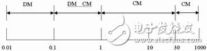
Fig.1 Distribution of common mode interference signal and differential mode interference signal of DC-DC converter
EMC design of DC-DC converter
Shielding and grounding
Shielding can effectively suppress electromagnetic interference propagating through space. There are two purposes for shielding: one is to limit the internal radiated electromagnetic energy to cross an area; the other is to prevent external radiation from entering a certain area. Shielding is one of the means to solve the EMC problem of DC-DC converters. The purpose is to cut off the electromagnetic wave propagation path, mainly to seal the casing of DC-DC converter. The main point of grounding is that the potential is the same, the internal circuits do not interfere with each other, and the external interference is resisted. Minimize the impedance caused by the inductance of the wire, increase the impedance of the ground loop, and reduce the interference of the ground loop.
Soft switching technology
The use of soft switching technology to achieve zero voltage switching and zero current switching operation can greatly reduce the di/dt and dv/dt of power devices. That is, the power tube can be turned off at zero voltage and turned off at zero current. If the fast diode is also soft-off, the EMI level of the DC-DC converter can be greatly reduced.
Optimized buffer circuit
Adding a snubber circuit to the drive circuit of the switch tube can also effectively reduce the di/dt and dv/dt in the circuit, thereby reducing the source of EMI interference. The snubber circuit delays the turn-on and turn-off process of the power switching device, thereby reducing the EMI level of the DC-DC converter. For the same type of switch tube, it is determined by experiment when other conditions are the same except that the drive buffer circuit is different.
For example, the converter A uses a drive circuit without a drive snubber resistor; the converter B uses a drive circuit of a 150 Ω drive snubber resistor anti-parallel diode. Usually the dv/dt of the switch is turned off much less than when it is turned on, and it has little effect on the EMI level of the DC-DC converter. There are diodes connected in anti-parallel, so that the turn-on speed can be slowed down, and the turn-off speed is not affected, which can ensure that the original machine efficiency is not affected to the utmost.
The experiment proves that the turn-on speed of the switch in converter B is much slower than that of converter A. The dv/dt of VDS is about 2V/nS when converter B is turned on, and the dv/dt of VDS when converter A is turned on. Around 5V/nS, it is much bigger. It can be seen that increasing the appropriate drive resistance and optimizing the drive circuit can significantly reduce the di/dt and dv/dt in the circuit and reduce the EMI level of the power supply DC-DC converter.
The EMI radiation emission test further verifies the effect of the size of the switching tube drive snubber resistor on the EMI level of the entire DC-DC converter. Figure 2 shows the radiated interference when the converter B is a non-pinch transformer with a drive resistance of 1 Ω and 47 Ω (diode in reverse parallel). It can be seen that after increasing the driving resistance, the frequency points of 30 MHz and nearly 200 MHz each have a significant improvement of 3_5 dB.
Drive resistance is 1Ω (horizontal direction)
Drive resistance is 47Ω (horizontal direction)
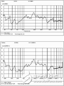
Figure 2 Effect of drive resistance on radiation emission
24V Power Supply, the current range is 2A-9.2A, the max power is 220w. We also can meet your specific requirement of the prodcuts.The material of this product is PC+ABS. All condition of our product is 100% brand new.
Our products built with input/output overvoltage protection, input/output overcurrent protection, over temperature protection, over power protection and short circuit protection. You can send more details of this product, so that we can offer best service to you!
24V Power Supply
24V Power Supply,24V Pc Power Supply,24V Dc Power Supply ,24V Power Supply For Pc
Shenzhen Waweis Technology Co., Ltd. , https://www.waweis.com