This paper introduces a design scheme of intelligent regulated power supply based on AT89C51. Its core technology is to change the output of the voltage regulator module after controlling the digital-to-analog conversion by AT89C51. The system consists of a rectification and filtering preliminary voltage regulator circuit, an AT89C51 control part, a DAC and a display part. The regulated power supply can be continuously step-adjustable and can be displayed in real time to make up for the shortcomings of the traditional regulated power supply.
The DC stabilized power supply studied by this system is mainly in line with the characteristics of intelligence, digitization and modularization: intelligent means that the system has programmable modules to intelligently control the system; digitization means that the system output voltage is displayed through the 7-segment digital tube, and The output voltage is continuously stepped digitally adjusted by pressing the button; the modular finger system is composed of various related modules, which improves the reliability of the system.
AT89C51 intelligent regulated power supply design principle
1, design system block diagram
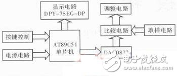
The system consists of modules, and the system block diagram of its modules is shown in Figure 1.
2, the composition of the module circuit design
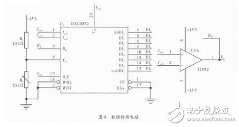
(1) Power circuit module design. Using LM7815, LM7915 series three-terminal regulator regulator circuit (circuit as shown in Figure 2) for the op amp TL082, single-chip AT89C51 and digital-to-analog DAC08 32 devices to provide a stable operating voltage, to achieve the system's operating voltage and system regulated power supply Continuous stepping is adjustable.
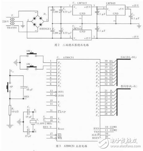
(2) AT89C51 main control module design. AT89C51 is the control core of the system. It mainly controls the regulated power supply by controlling the digital-to-analog conversion, and controls the display circuit. The circuit is shown in Figure 3.
The main control circuit includes the basic circuit of AT89C51 operation: reset circuit and crystal oscillator circuit. There are also two buttons: the +SW button and the -SW button, which are used to control the increase and decrease of the output voltage.
Battery is the energy source of AGV car, and also relates to the service life of AGV car.Common battery types for AGV vehicles include nickel-cadmium battery, nickel-metal hydride battery, lithium battery and lead-acid battery, which have the following characteristics:
The nickel-cadmium battery used in AGV car has large internal resistance and can be used for large current discharge.
2. Nimh battery
It offers higher capacity at the same price as nickel-cadmium batteries, less pronounced memory effects, and lower environmental pollution.
3. Lithium battery
"Lithium battery" is a kind of battery with lithium metal or lithium alloy as negative electrode material and non-aqueous electrolyte solution. Because lithium battery has the characteristics of high energy density, high voltage and stable operation, it is widely used.
4, lead acid battery
The electrodes are mainly made of lead and its oxides, and the electrolyte is a kind of battery with sulfuric acid solution.Lead-acid battery has the advantages of good invertibility, stable voltage characteristics, long service life, wide application range, abundant raw materials, renewable use and low cost.
Rechargeable Battery Pack,Lithium Ion Battery,Lithium Ion Rechargeable Battery,Portable Battery Pack
Xinxiang Taihang Jiaxin Electric Tech Co., Ltd , https://www.chargers.be