Abstract: The internal structure, functional characteristics and basic principles of the integrated chip UCC3626 for the brushless DC motor controller are introduced. The design method of using UCC3626 and IR2110 to form a three-phase brushless DC motor speed control circuit is given.
Keywords: Brushless DC motor; speed control; UCC3626
0 Introduction Brushless DC motor is a new type of DC motor with electronic commutation instead of brush commutation. It has the advantages of wide speed range, good control characteristics, high reliability, easy maintenance, no commutation sparks and no radio interference. Therefore, it is widely used.
UCC3626 is a three-phase brushless DC motor controller integrated chip produced by TI. It can provide high-performance three-phase, two-quadrant or four-quadrant controller design functions for brushless DC motors and can be input from the rotor position. The signal is decoded to output six control signals to drive the external power switching device. Its internal triangle wave oscillator and comparator, as well as hardware resources such as current sensing amplifier and absolute value circuit, can provide a broad platform for brushless DC motor control, thereby greatly simplifying the hardware design of the control circuit.
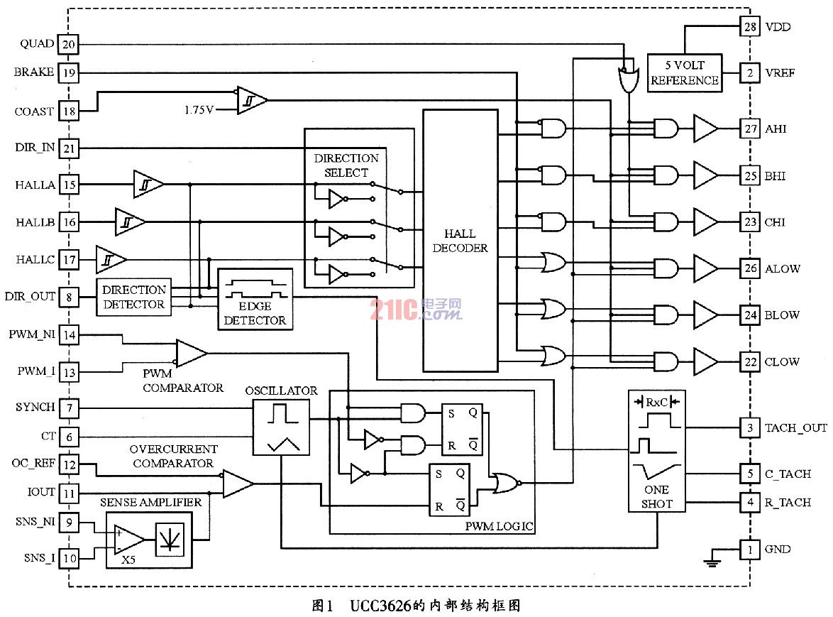
1 The structure and basic principle of UCC3626 UCC3626 contains a precision triangle wave oscillator and comparator, which can provide PWM control in voltage control or current control mode. Its external clock is input through SYNCH. The oscillator can be easily connected to an external clock. Synchronize. In addition, UCC3626 also has a QUAD selection terminal for selecting the four-quadrant or two-quadrant chopping control of the output power bridge, that is, to determine the high-side switch and the low-side switch, and at the same time, PWM control or only low-side switch PWM control. The differential current sensing amplifier and absolute value circuit in UCC3626 can establish a correct current for the control of the motor and provide current protection week by week. In addition, in order to achieve speed control, the device also provides a precision speed measurement circuit. Its TACH_OUT speed signal is a variable duty cycle frequency output signal, which can be directly used for digital speed control or provides an analog speed feedback signal after filtering. The COAST in UCC3626 can be used to control the start and stop of the motor. The BRAKE digital input can make the device enter the braking mode. DIR_IN and DIR_OUT are steering input and output control. The internal structure block diagram of UCC3626 is shown as in Fig. 1. The main features of its chip are as follows:
â—‡ Two-quadrant or four-quadrant operation control;
â—‡ Integrated absolute current amplifier circuit is integrated;
â—‡ Weekly current detection;
â—‡ With accurate variable duty cycle speed signal output;
â—‡ Contains precise triangle wave oscillator;
â—‡ With steering output function.
2 Control system circuit design
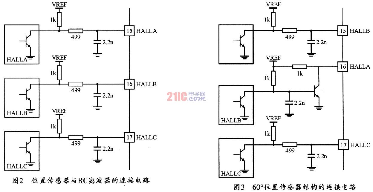
2. A position sensor The connection circuit of three position sensors of UCC and RC low-pass filter is shown as in Fig. 2. In the figure, the position signals generated by the three Hall position sensors can be connected to the UCC3626's HALLA, HALLB, and HALLC signal input terminals after being pulled up by a pull-up resistor and RC low-pass filter. The commutation logic truth table of UCC3626 is given, and the changes of six outputs (AHI, BHI, CHI, ALOW, BLOW, CLOW) with the inputs (BRAKE, DIR_IN, DIR OUT, HALLA, HALLB and HALLC) are also given. And change the decoding logic.
UCC3626 was originally designed for the 120 ° position sensor structure. If it needs to be used in the 60 ° C motor position sensor structure, the B-phase Hall signal can be connected to the HALLA terminal in the reverse direction as shown in Figure 3.

2.2 Speed ​​measurement signal The speed measurement signal TACH_OUT of UCC3626 comes from the internal accurate monostable circuit, usually triggered by the rising or falling edge of the three Hall position signals of HALLA, HALLB, HALLC, its frequency fT (Hz) and the pole of the motor The logarithm p, the speed n (r / min) have a direct proportional relationship:
fT = pn ï¼ 20
The monostable time tON can be determined by the capacitor R and capacitor C connected to the R_TACH and C_TACH pins: tON = RC
The speed measurement signal TACH_OUT can be used for digital closed-loop speed control of the microcontroller. After the speed signal TACH_OUT is filtered, the speed analog signal can be used for analog speed control. Figure 4 shows a simple analog speed control circuit connection method. The speed command signal in the figure can be connected to an external operational amplifier. .

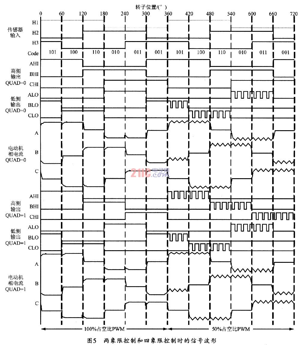
2.3 Two-quadrant or four-quadrant operation control Motors generally have four possible working quadrants. In two-quadrant control, the motor generally works in the I and III quadrants (the torque and speed are in the same direction). Because the brushless DC motor controller that works in two quadrants has no ability to decelerate the load except friction, this method is limited to less demanding occasions; four-quadrant control is required to provide four-quadrant work, which The torque and speed direction at the time are opposite, so the speed of the system movement can be improved.
UCC3626 can choose two-quadrant and four-quadrant control through QUAD terminal. When QUAD is 0, it is two-quadrant control. At this time, UCC3626 only performs PWM control on the low side of the power switch; while when QUAD is 1, it is four-quadrant control. At this time, the high-side switch and low-side switch perform PWM control . Figure 5 shows the main current signal waveforms under two-quadrant and four-quadrant control.
2. 4 power stage design UCC3626 can provide six driving signals for the main circuit power stage. For the case where no braking function is required but two or four quadrant control is required, the circuit shown in Figure 6 (a) can be used. In many cases, the system needs a braking function. At this time, the circuits shown in Figure 6 (b) and Figure 6 (c) can be used. In this circuit, each bridge arm requires a series diode, and the low-side freewheeling diode must be Ground to avoid braking current flowing through the lower half bridge. The circuit shown in Fig. 6 (c) is suitable for the occasions requiring braking function and four-quadrant control. The additional sensing resistor can be used to check the PWM OFF current.

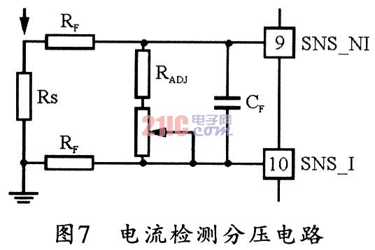
2. 5 current detection circuit The current detection circuit of UCC3626 includes a differential current sensor amplifier with a fixed gain of 5 and an absolute value circuit. Among them, the current sensing signal needs to pass the low-pass filter to remove the peak signal, and the amplifier's input impedance balance can achieve the best performance. If the sensor needs to be adjusted, the voltage divider circuit shown in Figure 7 can be used, which can be used to maintain impedance matching.
In the four-quadrant control, the circuit of the motor flowing through the sensing resistor may have reversed voltage polarity during the freewheeling period. The absolute value amplifier circuit can solve this problem. In fact, the output of the absolute value amplifier can reproduce the motor circuit. , And can be used for protection circuit and feedback loop.
3 Speed ​​control circuit based on UCC3626 175 V / 2 A quadrant speed control circuit based on UCC3626 and IR2110 is shown in Figure 8. The circuit is connected to the power MOSFET through three IR2110s. The speed command of the controller is taken from the potentiometer R30, and R11 and C9 can filter and buffer the TACH_OUT speed feedback signal. The amplifier U5A can provide small signal compensation of the speed control loop, and its output can control the PWM, and the integral capacitor C8 and The resistor R10 serves as a correction element.

4 Conclusion This paper introduces the structural characteristics, working principle and design method of the control system circuit of the special control chip UCC3626 for the brushless DC motor. UCC3626 can realize two-quadrant or four-quadrant control, as well as cycle-by-cycle current protection and speed closed-loop control. In addition, the brushless DC motor control system based on UCC3626 is simple in circuit, economical in price, high in reliability and good in stability. This circuit can be widely used when the motor control accuracy requirements are not high and the power requirements are not too large.
Fire resistant Control Cable, a kind of high quality fire resisting performance cable with special formula adding for its protective insulation and jacket such as PTFE ,mica tape or fiberglass yarn.. What makes this cable different from flame retardant cable is that fire resist cable will still keep electrical power on for a certain range of time in case of short circuits or combustion when fire happens. This cable should be used in public places to get a better safety and rescue capability.
Product Features
Long-term working temperature: -40℃ to 200℃
Rated voltage: 600/1000V
Conductor: Copper
Fire resistant material use: fiberglass yarn, mica tape, PTFE
Shielding material use: Tinned copper for screen


Application
This cable is applicable for below occasions with high fire resistant requirement:
Large-scale construction ,high-rise building
Petrochemical industry, power plants
Subway station, railway station, airport
Hospital, large library, military facilities
Underground shopping mall etc.
FAQ
Q: Are you a factory or trading company?
A : We are a manufacturer. We are professional in
developing and producing electrical wires and cables since 2001.
Q: Can I visit your factory?
A :Yes! You are welcome to visit our factory for further detail check.
Our factory is located in Minqing,Fujian. You could choose to fly to Xiamen/Fuzhou International airport. And tell us your flight No. We will arrange to pick you up if you like.
Q: May I buy samples from you?
A: Yes! You are welcome to place sample order to test our superior quality and services.
Q: Can you put my brand name (logo) on these products?
A: Yes! Our factory accepts to print your logo on the products.
Q: May I know the status of my order?
A: Yes .The order information and photos at different production stage of your order will be sent to you and the information will be updated in time.
To receive a quote, further information or advice, Leen Cable invites you to contact us. And you are also welcome to visit our factory if you would like to get closer to our production line.
Fire Resistant Control Cable,Fireproof Control Cable,Fireproof Sheathed Control Cables,Shielded Fire Resistance Control Cables
Smartell Technology Co.,Ltd , http://www.liencable.com