This paper proposes a TCP optimization method for the TD-HSUPA system: the radio network controller RNC (Radio Network Controller) is used to analyze the feedback packet information of the server on the TCP connection link, and the current TCP connection status is analyzed. Before the timeout occurs, the NodeB is controlled to give priority to the terminal and allocate more time slots and code channels in the short term, effectively preventing the wireless link from entering the "TCP slow start phase" and affecting wireless bandwidth utilization. The advantage of this method is that it only does TCP data packet analysis and processing in the RNC, does not affect the entire network, and has good system compatibility.
1 TCP optimization method of TD-HSUPA system
High-speed uplink packet access HSUPA (High Speed ​​Uplink Packet Access) is the uplink data transmission standard of TD-SCDMA. As a matching HSDPA high-speed downlink data transmission, HSUPA introduces HARQ by using NodeB-based fast scheduling, fast hybrid automatic retransmission request (Hybrid AutomaTIc Repeat Request), high-order modulation and enhanced dedicated channel E-DCH (Enhance-Dedicated Channel) and other key technologies, making the theoretical maximum uplink rate of TD-SCDMA 2.2 Mb / s, for online games, high-definition video calls and other services Provide sufficient bandwidth to enrich the application of 3G wireless communication.
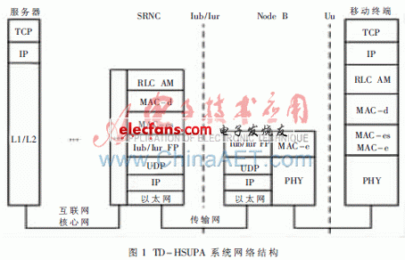
HSUPA's TCP data packet transmission process is: After the connection between the terminal, RNC and the remote server is established, the TCP data packet is sent by the terminal, received by the base station after wireless air interface transmission, and then the base station sends the data packet to the RNC through the transmission network. RNC provides a routing function to forward data packets to the core network and eventually reach the remote server. The protocol structure of the TD-HSUPA system is shown in Figure 1 [1].

In the HSUPA system, the sender of the data is the terminal, because not all terminals support the newer version of the transmission protocol such as TCP SACK, most terminals only support the standard TCP NewReno, so considering the compatibility of the system, the HSUPA system only Can mainly use TCP NewReno.
The effective means of optimizing TCP in wireless networks (such as TCP westwood [2], etc.) are mostly aimed at the sender of data. However, it is difficult for HSUPA system to improve all the terminals. From the network structure of HSUPA system shown in Figure 1, the optimization of HSUPA's congestion control can be considered by the receiver of the wireless link [3-4 ], Which is handed over to the RNC and the base station.
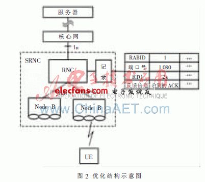
This paper presents a method for optimizing the TCP of HSUPA system in RNC and NodeB. The structure is shown in Figure 2.

The specific plan is as follows:
(1) The data is sent by the user equipment UE (User Equipment) and then passed to the RNC through the Node B. The RNC analyzes the TCP header information of each data packet, and the use of each user can be calculated by the formula Bw ′ = L / TInt [5] The bandwidth of the wireless link, where L is the packet size and TInt is the packet arrival time interval. According to the calculation result of Bw ′, the estimated bandwidth Bw can be calculated by the formula Bw = αBw + (1-α) Bw ′ [2], where? Is taken as the weighting coefficient to be 0.9, and 90% of the bandwidth calculation is derived from the previous value , Which is also an estimate of the smoothed bandwidth.
(2) The RNC does not know the time-out retransmission time RTO (Retransmission TImeout) of the UE, and can only estimate the value through other means. The RTO of a TCP connection is calculated based on the round-trip time RTT (Round-Trip Time) of the data packet. The RTT includes the delay of the wired link, the delay of the RNC forwarding, and the transmission delay of the wireless link. ) In parsing the data packet, it is easy to calculate the transmission delay tc of the wired link. The delay forwarded by the RNC is smaller than the value of the RTO, which can be considered as a fixed value tr. The delay of the wireless link can be expressed by the formula tw = Calculated by L / Bw, where L is the TCP / IP packet size, which can be set to 1 500 B, and Bw is the bandwidth calculated in step (1), so the RNC side can estimate the TCP timeout time RTO = 2 × (tc + tw + tr).
(3) After receiving the data packet, the server will send a data packet containing feedback information. When these data packets containing feedback information arrive at the RNC, the RNC needs to parse the TCP / IP header information of these data packets. If these feedback data are detected to contain With 3 repeated ACK messages, the RNC will send signaling through Iur to inform Node B to temporarily increase the scheduling priority of the UE in the next scheduling cycle and add a physical channel for the UE to expand the available bandwidth of the UE, so that the UE can be Retransmit the data to avoid entering the slow start phase. After an RTO time, Node B automatically restores the priority of the UE and the assigned physical channel.
In the above method, the RNC analyzes the cause of UE congestion based on the analysis of the feedback data packet. If congestion occurs less frequently, it means that the wireless air interface environment is causing jitter. The RNC calculates the bandwidth required by the UE according to step (1), and sends the calculated bandwidth value to the Node B. Let the Node B In the next period of time, the number of channels is increased to ensure that the UE can retransmit the data as soon as possible. If congestion occurs many times for a long time, it means that it is caused by other reasons. In the HSUPA system, this kind of problem is handled by RRM (Radio Resource Management), so you only need to set a silent time for this solution. After this program is executed once, a timer needs to be started, and the method is activated after a period of silence. The silence time should be determined according to the load of the network. If the overload is small, the time can be set to a shorter time. Longer.
The Shackle Insulator is made from high quality porcelain material, The Porcelain Shackle Insulator can endure high amount of temperature and current, Shackle Type Insulator usually used in low voltage distribution network.Such High Voltage Porcelain Shackle Insulator can be used either in a horizontal position or in a vertical position. Shackle insulator can be directly fixed to the pole with a bolt or to the Cross Arm .
Features
1.The tapered hole of the spool insulator distributes the load more evenly2.Minimizing the possibility of breakage when heavily loaded
3.Very reliable, with a proven track record. Over 80 years of experience
4.Easier to maintain, can be coated and washed
5.Easy to identify a damaged unit
The following shackle insulators comply with the BS standard, the glaze colour of the insulators are brown, light gray etc..
| MAIN DIMENSIONS AND STANDARD PARTICULARS | |||
| Type | ED-2(B) | ED-2(C) | |
| Main Dimensions | H | 76 | 80 |
| D | 89 | 80 | |
| d | 48 | 50 | |
| d1 | 21 | 22 | |
| R | 10 | 6 | |
| Transverse Stength,KN | 12.7 | 13.2 | |
| Power Frequence Flashover Voltage | Dry,KV | 25 | 25 |
| Wet,KV | 12 | 12 | |
| Net Weight, Each Approx., kg | 0.5 | 0.5 | |


We warmly welcome friends both domestic and abroad to visit our company, if you have any questions, please contact with us directly.
Shackle Insulator
Shackle Insulator,Shackle Type Insulator,Porcelain Shackle Insulator,High Voltage Porcelain Shackle Insulator
FUZHOU SINGREE IMP.& EXP.CO.,LTD. , https://www.cninsulators.com