The emergence of white LED lighting has solved the shortcomings of low luminous efficiency of the original lamps. However, when the outside is not particularly dark, if the indoor white LED lights are all turned on, it will cause unnecessary waste of power. Therefore, this paper proposes a smart lighting system that can automatically adjust the brightness of the white LED light according to the change of the natural light intensity of the outside world, and can turn on or turn off the wireless wirelessly through the ZigBee network, which not only saves time and effort, and has no additional wireless communication costs And, through Ethernet, remote monitoring can also be achieved.
1 Overall design plan
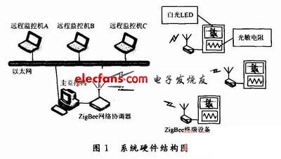
The intelligent dimming system is mainly designed for buildings such as classrooms and large office spaces. Therefore, taking a teaching building as an example, the overall design idea of ​​the solution is described. The hardware structure of the system is shown in Figure 1. The system is composed of remote monitoring machine, main monitoring machine, ZigBee network coordinator, ZigBee terminal equipment, white LED and light sensor.
The working process is as follows:
After the ZigBee network coordinator successfully sets up the network, the ZigBee terminal device is added to the network. The photoresistor collects the light intensity of the light intensity on the indoor working surface, transmits the collected real-time light intensity signal to the ZigBee terminal device, compares the detected value with the given value, adjusts the output PWM wave duty ratio, and can be adjusted Self-light LED light intensity; at the same time, the ZigBee terminal device transmits the light intensity signal just collected to the ZigBee network coordinator, and the network coordinator transmits the data to the main monitoring machine for display through the serial port; meanwhile, click a key Turn on the lights or turn off the lights with one click, you can turn on or turn off the white LED lights through the ZigBee network. In addition, through Ethernet, remote monitoring machines in different places can also control and monitor indoor lighting.
2 System hardware part 2.1 ZigBee network coordinator The hardware core of the system is CC2430 chip, and the ZigBee network coordinator and terminal nodes are composed of CC2430 chip. It is a true system-on-chip (SoC) COMS solution that can meet the 2.4 GHz ISM band application based on ZigBee, with low cost and low power consumption. It includes a high-performance 2.4 GHz direct-sequence spread-spectrum RF transceiver core and an industrial-grade small and efficient 8051 controller. The chip integrates a ZigBee radio frequency (RF) front end, memory and microcontroller.
The ZigBee network coordinator is responsible for tasks such as the establishment of the ZigBee network and the management of the nodes. It needs to process the received data and connect and communicate with the PC through the RS 232 serial port.
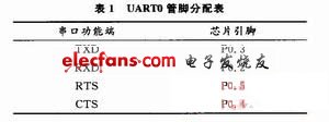
This system chooses UART0 of CC2430 as the serial port communication interface, and its corresponding pins are shown in Table 1.

In order to make the system work stably, the CC2430 chip requires a power supply voltage of 3.3 V. To this end, a voltage regulator circuit based on AMS1117-3.3 is designed to stabilize the voltage of about 5 V at 3.3 V.
The RS232 communication protocol can be used between the CC2430 and the PC to select the MAX232 chip to achieve the serial port level conversion function. The schematic diagram of the ZigBee network coordinator is shown in Figure 2.
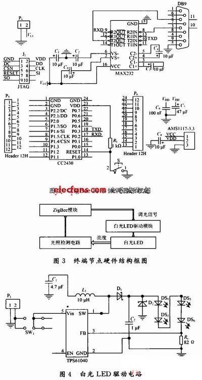
2.2 ZigBee terminal equipment The block diagram of the hardware structure of the terminal equipment is shown in Figure 3.
The working process is as follows: the voltage signal obtained by the light detection circuit is sent to the A / D conversion interface of the CC2430 chip, after internal programming, the white LED driver chip TPS61040 input control terminal EN control signal is adjusted by adjusting the PWM wave duty Stabilize the current driving the white LED light to the required light intensity.
Photoresistor is an economical and reliable photoelectric conversion device. Using its light guide effect, when light shines on the photoresistor, the resistance value drops. The system design uses MG41 type photoresistor.
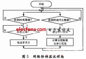
The system uses a constant current drive circuit, using TI's TPS61040 chip. The switching frequency of the TPS61040 is up to 500 Hz. Since the MOSFET connected to the SW pin inside the chip is a low-resistance integrated power FET, it helps to achieve extremely high efficiency. The TPS61040 white LED drive circuit designed in this paper is shown in Figure 4. This circuit can realize functions such as load disconnection, overvoltage protection, PWM dimming and so on.
3 System lower computer software design 3.1 Network coordinator node design The network coordinator of this system has two tasks, one is to communicate with the PC and transfer data to each other; the other is to communicate with other terminal devices through ZigBee, and its software flow As shown in Figure 5.
Home and indoor or building air filters remove unwanted particles like dust, pollen, pet dander and mold and ensure even the most allergy prone can breathe easily year–round. However, choosing the right filter for your home can be a rather involved process. To help, here are the most common indoor air filters and what each of them provides. The filters are the simplest basic component for air filtration solution through your heating and cooling system ,It is important that you constantly monitor the buildup of debris on these filters as well because it can easily be recycled into the air supply. It is easy change and maintain.
Indoor Air Purification Filter & Air purifier filter
AC Filter,Air Conditioner Filter,AC Furnace Filter,Home AC Filter
Donguan Bronco Filter Co., Ltd , https://www.broncofilter-cn.com