Keywords: DC resistance, degaussing dynamic test, digital signal processor
1 Introduction Transformer winding DC resistance test is one of the main items of the transformer factory and preventive tests. According to the IEC standard and the national standard GB1094, this test must be carried out during the manufacturing process, after overhaul, handover test and preventive test, as well as the determination of the average temperature rise of the winding and fault diagnosis [1].
In recent years, the test methods for DC resistance of power transformers have been discussed in detail in references [2 ~ 4]. These methods can be divided into two categories: static and dynamic measurement methods. The so-called static measurement method refers to the measurement after the winding charging current is stabilized. It includes the circuit mutation method to increase the loop resistance, the high voltage charging low voltage measurement method, the magnetic flux pump method, etc. They all have the disadvantage that the measurement process must rely on manual intervention . The so-called dynamic measurement method refers to the need to wait for stability before measuring, but to use the voltage and current data in the charging process of the inductor to measure its resistance. In the dynamic measurement method, the second-order oscillation method has higher requirements for the capacitors connected in series in the loop, and it is also necessary to strictly grasp the current extreme value point. If di / dt ≠0 and the value of the inductance is very large, the resulting Inductor voltage drop UL = Lx (di / dt) is superimposed on the voltage drop UR with a very small DC resistance, which reduces the measurement accuracy. Generally speaking, the static measurement method takes a long time, but the measurement data is more reliable; the dynamic measurement method is fast and efficient, but the measurement data is sometimes less reliable.
In this paper, according to their respective characteristics, with the help of TI (TexasInstrument) company's signal processor (DSP), the "demagnetization dynamic method" is proposed, trying to integrate the advantages of the two types of methods into one, to solve the intelligent, fast and reliable measurement of large power The problem of equipment DC resistance, especially the rapid measurement of large-capacity three-phase five-post transformers.
2 Principle analysis of test system
2.1 The basic idea of ​​the demagnetization method The conventional method of studying the three-phase three-post transformer is to equate the winding of the power transformer with the series connection of inductance and resistance, and the process of winding current change is 
Among them, Ï„ = Lx / Rx is the loop time constant; Rx and Lx are the DC resistance and inductance of the transformer winding under test; E and i are the power supply and loop current.
The following briefly analyzes the circuit transition process of the mutual inductance coupling winding of the three-phase five-post transformer, and its equivalent circuit is shown in FIG. 1. Among them, R1 is the primary resistance; R2 is the equivalent value of the secondary resistance; L is the inductance corresponding to the excitation reactance. The impedance function of this circuit is: ![]()

The forced response (ie the steady-state component of the terminal voltage) and the natural response of this circuit are: ![]()
The full response of the circuit is the sum of the forced response and the natural response, ie, ![]()
The undetermined constant A can be obtained from the initial conditions. Therefore, the time-varying function of the terminal voltage is: ![]()
Then, if a constant current source is passed into the transformer short-circuited to the secondary side, although the primary current quickly reaches its stable value, due to the influence of the inductor current induced by the secondary side, the primary voltage will reach its value after a long time. Stable value. It can be seen that the transition process of the mutual inductance coupled winding circuit is determined by the secondary parameters, and has nothing to do with the primary. Even increasing the internal resistance of the power supply cannot affect the secondary time constant.
The reason for the transient process of the inductive winding after power-on is that the magnetic flux cannot be abruptly changed. The transition time is required when switching from one steady state to another steady state. If the residual magnetism is omitted, the initial state magnetic flux is zero when measuring the DC resistance of the transformer. If we manage to maintain this zero state throughout the measurement process, then the transition process is fundamentally eliminated and the purpose of rapid measurement is achieved.
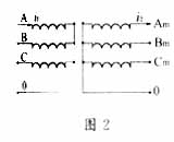
While measuring the DC resistance of the high (medium) voltage coil, the reverse current is added to the medium (low) voltage coil to cancel the current magnetic field. In other words, when measuring the DC resistance of the high voltage side, in addition to adding current to the high-voltage phase coil to be tested, a reverse current should be added to the corresponding medium-voltage side coil to make the magnetic potential generated by this current and the high-voltage side The generated magnetic potentials are equal in magnitude and opposite in direction, and if they can be added simultaneously, the performance will cancel each other out. That is, to ensure that the "zero flux" state is maintained throughout the measurement process. The schematic diagram is shown in Figure 2 (omitting the low-voltage winding).
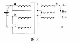
When measuring the low-voltage winding, its simplified circuit is shown in Figure 3. It can be seen from the figure that the turns ratio of medium and low voltage is the ratio of medium voltage line voltage and low voltage line voltage. If the medium voltage line voltage is u2 and the low voltage is u3, then N2 / N3 = (u2 /
 / u3. And because the low-voltage winding system is connected in series with bc phase and parallel with a phase. Therefore, the total injection current should be 1.5 times the a-phase current, that is,
 Satisfying the relationship of (8) can make the medium and low voltage magnetic potentials cancel each other out. Through the DSP control constant current source output demagnetization current size, complete the test.
2.2 The basic idea of ​​the dynamic test method The static method alone cannot solve the contradiction between the accuracy and rapidity of the measurement. To this end, this article proposes a "dynamic" test method based on the idea of ​​"static" measurement. The schematic diagram of its principle is shown in Figure 4. In the figure, UN is the voltage at the upper end of the high-precision standard resistor RN serially connected to the winding, and E is the voltage at the winding end under test.
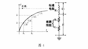
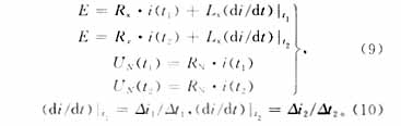
Theoretically, the smaller the value of Δt, the more accurate the direct resistance value RX solved by equations (9) and (10), then it is not a problem to ensure the accuracy of the measurement, but this is not the case. When Δt is small to a certain degree, the error of the calculated RX value will increase as Δt decreases. This is because the word length in the computer operation, the quantization error during the analog / digital conversion of the analog signal and the natural time constant of the coil all have an influence on the calculation result of the direct resistance RX. The dynamic test method must go through careful research and a large number of simulation tests before the optimal measurement plan can be obtained. However, after passing the demagnetizing current during the measurement process, the change in current is relatively stable (ie, Δi is small), and the number of sampling points can be obtained less. Therefore, the value of Δt can be relatively larger, reducing the microprocessor. Computing burden. The tester determines the number of sampling points according to the following formula:
In equation (11), Δi and δ are set by the computer in advance. The voltage is continuously sampled within the time interval of Δt (preliminarily set by the computer) and judged. Once the requirements are met, the voltage is not sampled and data processing is performed to complete functions such as display and PC communication.
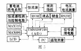
3 Test System Introduction The entire test system takes TMS320F240 as the control center, and the system block diagram is shown in Figure 5. The TMS320F240 (16-bit fixed-point processor) integrates high-performance DSP cores and rich microcontroller peripheral functions into a single chip, making it ideal for traditional multi-processor units (MCU) and expensive multi-chip designs Alternatives [5]. F240 has a 16-channel 10bit A / D input interface. Due to its excellent performance, it can basically complete all the functions of the system by relying on a single chip. Compared with the conventional design, the use of the F240 chip makes the system hardware circuit simple, volume reduced, and software Programming also becomes easy. In order to realize the functions of this system, the F240 external expansion 64Kbyte data storage unit is used for data processing and storage; the MAX715 chip is used to provide multiple voltages required by the system; the power monitoring chip MAX691 ensures the normal supply of power, the write protection of the RAM and the system Low-voltage detection function; MAX232 chip is used for the communication interface; the REF02 precision voltage / temperature sensor chip is selected to measure the ambient temperature at the same time; the user interface is equipped with a 192 × 128 dot matrix liquid crystal display and a 4 × 4 keyboard to facilitate parameter display and user ’s various Various functional operations; data collection, edge capture, "watchdog", and program storage are all implemented by F240. Before the test, clamp all the test clamps to the transformer terminals, and change the measurement terminals under the control of the computer.
4 Measurement tasks
4.1 Calculate the unbalance rate of phase-to-phase resistance and line-to-line resistance [4]
In GB6451-86 "Three-phase immersed power transformer technical parameters and requirements" series of standards, the three-phase winding DC resistance unbalance rate limit is specified. When the capacity is 1600kVA, the phase resistance unbalance rate ≤ ± 4%, line resistance unbalance rate ≤ ± 2%; when the capacity is larger, the phase resistance unbalance rate (when the neutral point is drawn out) and the line resistance are not The balance rate is ≤ 2%. Therefore, the corresponding resistance unbalance rate must be calculated based on the measurement results.
4.1.1 Expression of phase and line resistance unbalance rate Set the resistance values ​​of three phase windings of three-phase transformer as Ra, Rb and Rc; set the maximum phase winding and the minimum phase winding as Rmaxp and Rminp respectively. Therefore, according to the definition of the phase resistance unbalance rate Sp, there are: 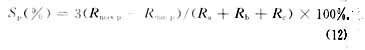
The line resistances set between any two terminals of the three line ends a, b, and c of the three-phase transformer are respectively expressed as Rab, Rbc, and Rca, and let Rmaxl be the largest and Rminl be the smallest. Therefore, according to the definition of the line resistance unbalance rate Sl: 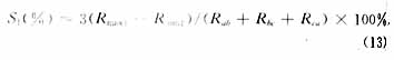
4.1.2 Expression of line resistance unbalance rate when Y or Z connection is seen from the perspective of measuring current resistance with DC power supply, Y connection and Z connection are not different, they are:
Rab = Ra + Rb,
Rbc = Rb + Rc,
Rca = Rc + Ra.
When Ra is the largest and Rc is the smallest, then Rab is the largest and Rbc is the smallest. Then equation (13) is transformed into: 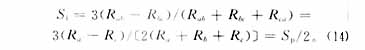
It can be seen from equation (14) that the line resistance unbalance rate S1 at the time of Y connection and Z connection is always equal to half of the phase resistance unbalance rate Sp.
4.1.3 Calculation of line resistance unbalance rate during D connection When D connection is used, the measured line resistance is obtained by connecting two phase windings in series and then in parallel with the third phase winding. Let Ra be the largest and Rc be the smallest, so the line resistance unbalance rate Sl is: 
4.2 Conversion of winding DC resistance value R75 The resistance of the transformer winding is affected by temperature. When measuring, the current ambient temperature should be recorded (preferably the winding temperature should be measured). Transformers without oil immersion are tested at room temperature. If the oil has been immersed, the oil surface temperature is used as the test temperature. If the temperature of the winding is much higher than the room temperature after the transformer is running, it is best to wait for the temperature to stabilize before measuring. For the conversion method of R75, please refer to the relevant information, which is omitted here.
6 Conclusion The characteristic of this method is that the static and dynamic test methods are organically unified reasonably. It is especially suitable for the winding DC resistance of power transformers with different capacities, different connection groups, and iron cores with five or three columns Fast, accurate and reliable measurement; another feature of this method is the reasonable selection of DSP digital processor, which can quickly and accurately perform data processing; due to the use of battery power supply, no need to add new equipment, this method is extremely easy Implemented on site.
2 Li Mankun, etc. The method and characteristics of large-scale power transformer DC resistance test. Transformer, 2000, 37 (7): 36 ~ 39
3 Li Weibo, Mao Chengxiong, Lu Jiming, etc. Research on Intelligent Tester for DC Resistance of Large Power Equipment. Metrology and Testing Technology, 2001, 28 (5): 22 ~ 234 Liang Zhirui, etc. Research on dynamic measurement of large inductance electrical equipment parameters. Journal of Electrical Engineering and Technology, 1998 (5): 41 ~ 43
5 Yu Xiang, Lu Jiming, Mao Chengxiong, etc. DSP serial communication. Electronic Engineer, 2002, 28 (11): 11 ~ 13
6 Zhang Bin, etc. Servo drive method that can control multiple motors in sequence. Journal of Electrical Engineering and Technology, 2000 (6): 25 ~ 27
7 Zhang Yiying. The mathematical relationship between the three-phase transformer DC line resistance unbalance rate and the phase resistance unbalance rate. Transformer, 1996 (7): 18 ~ 20 â–
12 Degree Travelator,Passenger Elevator Motor,12 Degree Moving Walkways,Passenger Panoramic Elevator
XI'AN TYPICAL ELEVATOR CO., LTD , https://www.chinaxiantypical.com