| Abstract: New cellular phone designs require a small form factor while maintaining good sound quality. Loudspeakers are the main factor restricting ultra-thin design. Ceramic speakers or piezoresistive speakers have opened the door to a new generation of mobile phone designs. Considering the capacitive characteristics of ceramic speakers, some considerations are required when choosing an amplifier to drive the speaker. Today's portable devices require smaller, thinner, and more power-saving electronic components. For compact mobile phones, moving-coil speakers have become a limiting factor for manufacturers to produce ultra-thin phones. Driven by this demand, ceramic or piezoelectric speakers are rapidly emerging as alternatives to moving coil speakers. Ceramic speakers can provide extremely competitive sound pressure levels (SPL) in ultra-thin, compact packages, and have great potential to replace traditional moving coil speakers. The difference between moving coil speakers and ceramic speakers is shown in Table 1. Table 1. Advantages and disadvantages of ceramic speakers and moving coil speakers
Amplifier circuits that drive ceramic speakers have different output drive requirements than traditional moving coil speakers. The structure of the ceramic speaker requires the amplifier to drive a large capacitive load and output more current at a higher frequency while maintaining a high output voltage. Characteristics of ceramic speakers The production process of ceramic speakers is similar to that of multilayer ceramic capacitors. Compared with moving coil speakers, this manufacturing technology allows speaker manufacturers to more strictly control the tolerances of speakers. Strict tolerance control is very important to weigh the choice of speakers, and also affects the repeatability of the audio characteristics of different production batches. The equivalent impedance of the ceramic speaker at the driver amplifier end can be approximated as an RLC circuit mainly composed of a large capacitor (Figure 1). In the audio frequency range, ceramic speakers are usually capacitive. The capacitance characteristics of the speaker determine its impedance decreases with increasing frequency. Figure 2 shows the relationship of ceramic speaker impedance with frequency, which is similar to a 1µF capacitor. The impedance has a resonance point, at which point the loudspeaker has the highest sound production efficiency. The drop in the impedance curve around the 1kHz frequency indicates the resonant frequency of the speaker. 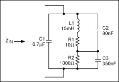 Figure 1. The ceramic speaker is mainly represented by a large capacitive load 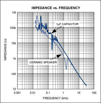 Figure 2. Ceramic speaker impedance vs. frequency, very similar to 1µF capacitor The relationship between sound pressure and frequency and amplitude. The AC voltage across the ceramic speaker causes the piezoelectric film in the speaker to deform and vibrate; the amount of displacement is proportional to the amplitude of the input signal. The vibration of the piezoelectric film causes the surrounding air to flow, thereby making sound. When the speaker voltage increases, the piezoelectric element deforms more and forms a larger sound pressure, which increases the volume. Ceramic speaker manufacturers usually specify the maximum driving voltage of the speaker, a typical value of 15VP-P. The offset of the ceramic device reaches the limit when the voltage is maximum. When the applied voltage is greater than the rated voltage, the sound pressure will not increase, but the distortion of the output signal will increase. Figure 3 shows the relationship between the output sound pressure (SPL) and frequency of the ceramic speaker at the maximum voltage. By comparing the graph of the relationship between SPL and frequency and the graph of the relationship between impedance and frequency, it can be clearly seen that the piezoelectric speaker produces the highest SPL at the highest efficiency at the self-excited frequency. 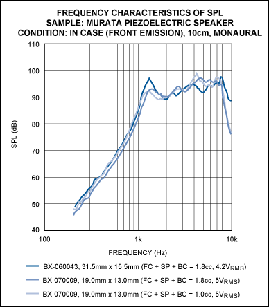 Figure 3. Distortion of the output signal increases when the voltage is greater than the speaker's rated voltage The requirements for driving ceramic speakers to the amplifier. The ceramic speaker manufacturer specifies the maximum voltage, that is, the maximum sound pressure from 14VP-P to 15VP-P. In this way, the question becomes how to generate these voltages when powered by a single power supply. One solution is to increase the battery voltage to 5V with a switching regulator. With a 5V voltage, system designers can choose a single-supply amplifier that bridges the load (BTL). Bridging the load can produce a voltage doubling effect on the speaker. However, when a 5V single power supply is used to power a BTL amplifier, the output voltage is theoretically only 10VP-P swing. At this voltage, the ceramic speaker cannot output the highest SPL. In order to get a higher SPL, a higher power supply voltage must be used. Another approach is to use a boost converter to adjust the battery voltage to 5V or higher. This solution also has its own problems-that is, the size of the required device. The size of the overall scheme can be judged according to the peak value of the inductor current. In order to ensure that the magnetic core will not be saturated, the size of the inductor must be large enough. Large current and small size inductors can also be found on the market. However, the core saturation current rating of this type of inductor may not be sufficient to meet the requirements, and it cannot provide the high voltage and large load current required to drive the speaker under high frequency conditions. Driving ceramic components requires large currents while avoiding current limiting. This is because the impedance of the ceramic speaker is very low at high frequencies. The amplifier used to drive the ceramic speaker must have a sufficiently large drive current so that when a large amount of high-frequency components enter the speaker, the device will not enter the current limiting mode. Figure 4 shows the application circuit of the MAX9788 Class G amplifier. Class G amplifiers have two power supply voltage amplitudes, high voltage and low voltage. When the output signal is small, the low voltage power supply is used; when the output signal requires a higher voltage swing, the high voltage is switched to the output stage for power supply. Since the class G amplifier has a low-voltage power supply, when the output signal is small, the efficiency is higher than the class AB amplifier. Due to the high-voltage power supply, Class G amplifiers can withstand transient peak voltages. 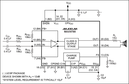 Figure 4. Typical ceramic speaker application circuit using MAX9788 The MAX9788 in Figure 4 uses an on-chip charge pump to generate a negative supply voltage opposite to VDD. When the output signal requires high-voltage driving, the negative power supply voltage acts on the output stage. The MAX9788 provides an optimized solution for driving ceramic speakers, which is more efficient than traditional solutions using class AB amplifiers and boost converters. Loudspeaker manufacturers usually recommend a fixed resistor (RL) in series with ceramic speakers, as shown in Figure 4. When the signal contains a lot of high-frequency components, use this resistor to limit the current output of the amplifier. In some applications, if the frequency response bandwidth of the audio signal transmitted to the speaker is limited, this fixed resistor may not be used. For amplifiers, the use of resistors ensures that the speakers are not short-circuited. The capacitance of existing ceramic speakers is about 1µF. The impedance of the speaker in Figure 4 is 20Ω at 8kHz and 10Ω at 16kHz. In the future, ceramic speakers may have a larger capacitance, so that the amplifier can provide more current at the same frequency. The efficiency of ceramic speakers and moving coil speakers The efficiency of traditional moving coil speakers is easy to calculate. The audio coil winding can be approximated as a fixed resistance in series with a large inductance. If the speaker resistance is known, Ohm's law can be used to calculate the load power (P): P = I²R, or P = V × I. Most of the power of the speaker is converted into the heat of the coil. Since ceramic speakers have capacitive characteristics, the heat generated when consuming power is not high. Ceramic speakers consume "reactive" power. The reactive power is very small and is related to the loss factor of the ceramic device. Reactive power produces very little heat. When calculating reactive power, the formula P = V × I should not be used directly; ¹ should be calculated using the following formula: P = (πfCV2) × (cosΦ + DF) among them: C = speaker capacity V = RMS drive voltage f = driving voltage frequency cosΦ = phase angle between speaker current and voltage DF = speaker loss factor, DF value is very low, depends on signal frequency and speaker ESR Since the phase angle between the ideal capacitor voltage and current is 90 °, and the ceramic speaker is basically capacitive, cosΦ is equal to zero, so the capacitor part of the ceramic speaker model will not generate any power consumption. The inherent disadvantages of ceramic materials and dielectrics cause the speaker voltage to lag behind the speaker current by a phase angle, which is not exactly equal to 90 °. The small difference between the ideal phase shift (90 °) and the actual phase shift is defined as the loss factor (DF). The DF of a ceramic speaker can be equivalent to a small equivalent series resistance (ESR) in series with an ideal capacitor. Do not confuse series resistance with the isolation resistance between the amplifier and the speaker. DF is the ratio of ESR and capacitive reactance at the required frequency: 2, 3 DF = RESR / XC For example, a ceramic speaker with a capacitance of 1.6µF and an ESR of 1Ω, when driven by a 5VRMS, 5kHz signal, the reactive power is: P = (π × 5000 × 1.6e-6 × 52) × (0 + 0.05) = 31.4mW The difference between active power and moving coil speakers is that although ceramic speakers themselves do not consume active power, heat is generated in the driver amplifier output stage and the external resistance (RL) (Figure 4) between the amplifier and the speaker. The larger the external resistance value, the greater the dissipated power shared by the amplifier, at the expense of low-frequency response characteristics. When driving a ceramic speaker with a 10Ω series resistance, the reactive power in the total load power does not account for much. Most of the power is dissipated in the external resistor. Figure 5 shows the relationship between amplifier power and frequency. 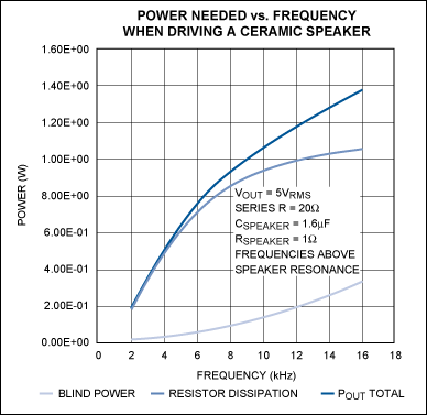 Figure 5. Reactive power accounts for a small percentage of the total load power of the ceramic speaker, and the main power is dissipated in the external resistor In order to obtain a better low frequency response, a small external resistor should be selected, but it will require the amplifier output stage to dissipate more power. The efficiency of the amplifier determines the output stage power of the amplifier. To obtain high-power amplifiers, high-efficiency solutions such as Class D and Class G amplifiers are required. A resistor is connected in series with the load end, so that the power is consumed in the load network instead of the speaker. Even if the efficiency of the amplifier is 100%, power will be dissipated in the series resistor, not the speaker. Take Figure 5 as an example. At 5kHz, the total power provided to the load is 629mW. An amplifier with an efficiency of 53% consumes 558mW. The power consumption of the amplifier determines the package size of the actual device. If a high-frequency sine wave must be used to drive the ceramic speaker, a large amount of power will be consumed. Conclusion The compact, thin and light design of portable devices is the main driving force behind the demand for small ceramic speaker applications. Ceramic speakers are different from traditional moving coil speakers, and new design solutions should be considered. The capacitance characteristics of ceramic speakers require the amplifier to have a high output voltage and a large output current to maintain high-voltage driving within the operating frequency range. When choosing an amplifier that drives ceramic speakers, it must be able to provide reactive power and active power for complex loads. In order to support the small size and low cost solution, the amplifier is required to have a high working efficiency. In order to meet the above requirements, it is necessary to adopt a topology different from the traditional class AB amplifier. More effective solutions, such as Class G or Class D amplifiers, have become very attractive solutions. Taking into account the cost, number of components and other indicators, Class G amplifiers are the best compromise solution. References "Blind Power Dissipation in a Piezo Ceramic Load (for a Sine Wave)," Sonitron NV. "Piezoelectric Transducers: Distributed Mode Actuators," National Semiconductor, "Application Notes for Multilayer Ceramic Capacitors," Kemet Electronics, FB56FCB5EBB9053CA2570A500160913 / $ file /F3101ECerLdPerfChar.pdf | ||||||||||||||
Protective Suit,Protective Personal Suit,Medical Isolation Gown,Disposable Isolation Gown
Ningbo Anbo United Electric Appliance Co.,ltd , https://www.airfryerfactory.com