Research on High-resolution Angle Measurement Technology of Millimeter Wave Terminal Guidance Radar in Frequency Domain
Aiming at the problem of poor angle tracking accuracy of millimeter wave terminal guidance radar, a single pulse angle measurement algorithm based on high resolution image in frequency domain is proposed. The algorithm is based on the principle of monopulse radar angle measurement. Before the angle measurement, the echo signals of the sum and difference channels are imaged in one-dimensional frequency domain, and then the amplitude measurement is performed in the frequency domain to obtain the angle error of the frequency domain unit. Filtering process to obtain the spatial angle of the radial geometric center of the target. Simulation results show that the algorithm can greatly improve the angle measurement accuracy of monopulse radar.
Keywords: monopulse; angle measurement; high resolution in the frequency domain; Doppler frequency shift; millimeter wave terminal guidance radar
0 INTRODUCTION Precision guidance technology is the key technology for precision guidance weapons. Its focus is on researching the final guidance technology to ensure that the weapons sought are in the complex battlefield environment and even the critical parts of the target. With the development of precision guidance technology for missile homing, when the radar seeker approaches the target, the flicker of the target angle has become the main source of tracking error for microwave / millimeter wave radar seekers, especially when tracking large extended targets. Angular flicker has become a major obstacle to improving the accuracy of terminal guidance radar. Therefore, it is a key technology of the terminal guidance radar to suppress the angle flicker and improve the angle measurement accuracy of the terminal guidance radar.
Classical methods for suppressing angular flicker are to receive and filter the backscattered echoes of the target in different spaces, frequencies and polarization modes according to different radar systems and application backgrounds. In recent years, with the development and application of broadband radar, the single-pulse angle measurement technology based on high-resolution range profiles has great potential and application prospects in suppressing angular flicker. The angle measurement algorithm based on frequency domain high resolution proposed in this paper is applied to millimeter wave PD system terminal guidance radar. It is to perform frequency domain high resolution imaging of the target echo under the condition that the system Doppler resolution meets certain conditions. The target frequency center unit of the target scattering center is detected in the method, the corresponding azimuth and pitch angles are respectively obtained for the detected frequency domain unit, and after a certain filtering process, the spatial angle of the target's radial geometric center is obtained. Simulation results show that the frequency-domain high-resolution angle measurement technology can effectively improve the angle measurement accuracy of the terminal guidance radar.
1 High-resolution principle in frequency domain When the missile and the target have relative radial motion, a Doppler effect is generated. For active terminal guidance radar, the Doppler frequency of the point target echo is: ![]()
In the formula: Vr (t) is the relative radial velocity of the projectile; λ is the wavelength of the transmitted signal. The relative speeds of different parts of the target and the missile are different, and the echo Doppler frequencies corresponding to different parts are also different. For millimeter-wave radar, the target characteristics are in the optical zone. Since the size of the target is much larger than the wavelength of the radar emission signal, the target can be regarded as an extended target composed of multiple scattering centers. When there is an angle between the line of sight of the seeker and the target, the direction of the speed of the scattering center of different parts of the extended target is different from the direction of the line of sight of the radar, which makes the Doppler frequency of each scattering center also different. If the frequency domain resolution of the radar system meets the requirements, the Doppler frequency of each strong scattering point of the body target can be resolved, and then the Doppler frequency information of each scattering point on the body target can be obtained in the frequency domain, thereby obtaining High-resolution one-dimensional image in the frequency domain.
2 Frequency domain high resolution angle measurement algorithm
2.1 Principle of amplitude and difference monopulse angle measurement Monopulse radar belongs to simultaneous lobe angle measurement. The radar antenna has two partially overlapping beams in an angular plane. The basic method for amplitude and difference monopulse radar to obtain the angle error signal is to perform the sum and difference beam processing on the signals received by the two beams at the same time. The difference signal, where the difference signal is the error signal in the angular plane.
Taking the azimuth plane as an example, assuming that the directivity functions of the two beams are exactly the same, set to F (θ), the amplitudes of the signal voltages received by the two beams are E1 and E2, and the declination of the two beams with respect to the antenna axis is δ Then for a target that deviates from the antenna axis θ, the sum signal amplitude is:

Among them: F2∑ (θ) is the transmit and beam directivity function, and F (δ-θ) + F (δ + θ) is the receive and beam directivity function, which is exactly the same as the transmit and beam directivity function; A is Scale factor.
The amplitude of the difference signal is:

Among them: F △ = F (δ-θ) -F (δ + θ) is the directivity function of the receiving difference beam.
Assuming that the error angle of the target is ε, the amplitude of the difference signal can be expressed as:
![]()
Since ε is relatively small, the Taylor series of F △ (ε) can be expressed as F ′ △ (0) ε, then:

Therefore, within a certain range of error angles, the amplitude of the difference signal is proportional to the error angle ε. The phase of the difference signal indicates that the target deviates from the antenna axis, so the error angle can be expressed as:

Among them, when the difference signal and the sum signal are in phase, ψ takes O, otherwise takes π.
2.2 Frequency-domain high-resolution angle measurement algorithm PD radar has three echo receiving channels, namely the sum channel, the azimuth channel and the pitch channel, denoted as E, △ f, △ y. Three-channel high-resolution one-dimensional image in the frequency domain. The target detection of the one-dimensional image of the and channel can obtain the Doppler position information of the strong scattering point, and then the azimuth error εfi and the pitch angle error εyi of each scattering point can be obtained according to the principle of single pulse off-axis angle measurement:

Filtering the angular error of each scattering point can obtain the angular error of the target geometric center, namely:

Among them, ai, βi are weighting coefficients.
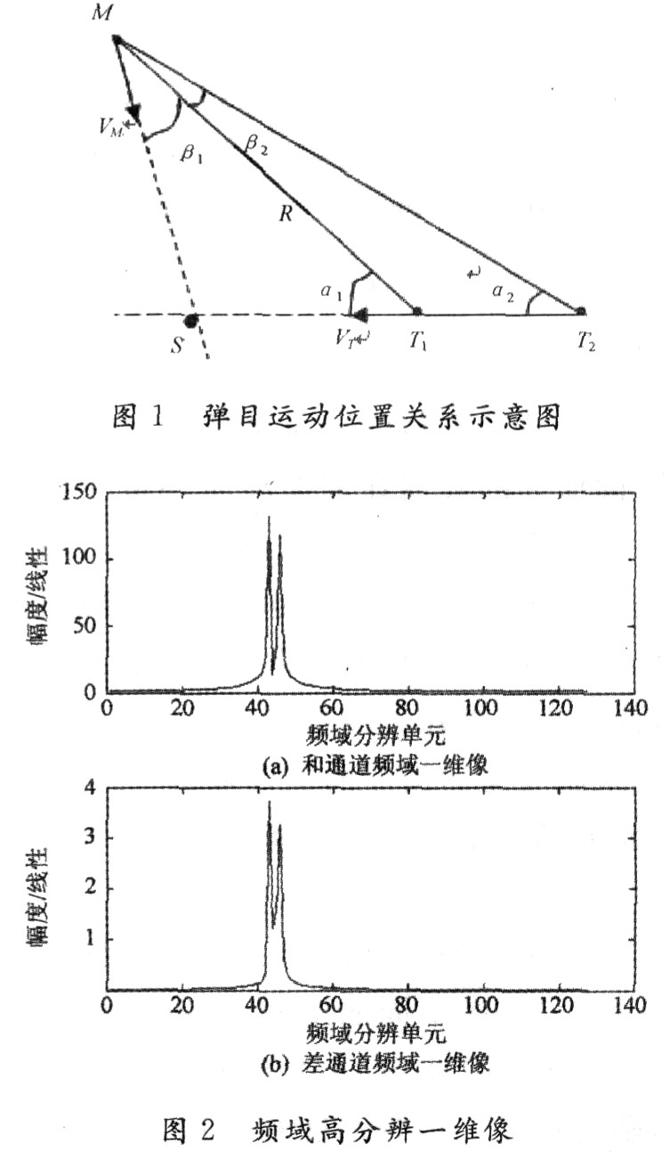
3 Simulation experiments In order to verify the effectiveness of the algorithm, simulation experiments were conducted. The positional relationship between the missile and the target is shown in Figure 1. The missile's movement speed VM is 450 m / s, and the target's movement speed VT is 1 000 m / s. α1 is 30 °, the target length is 20 m, and the two scattering centers of the head and the tail are taken. The high-resolution one-dimensional image in the frequency domain is shown in Fig. 2, where the frequency resolution is 100 Hz when the projectile distance is 150 m.

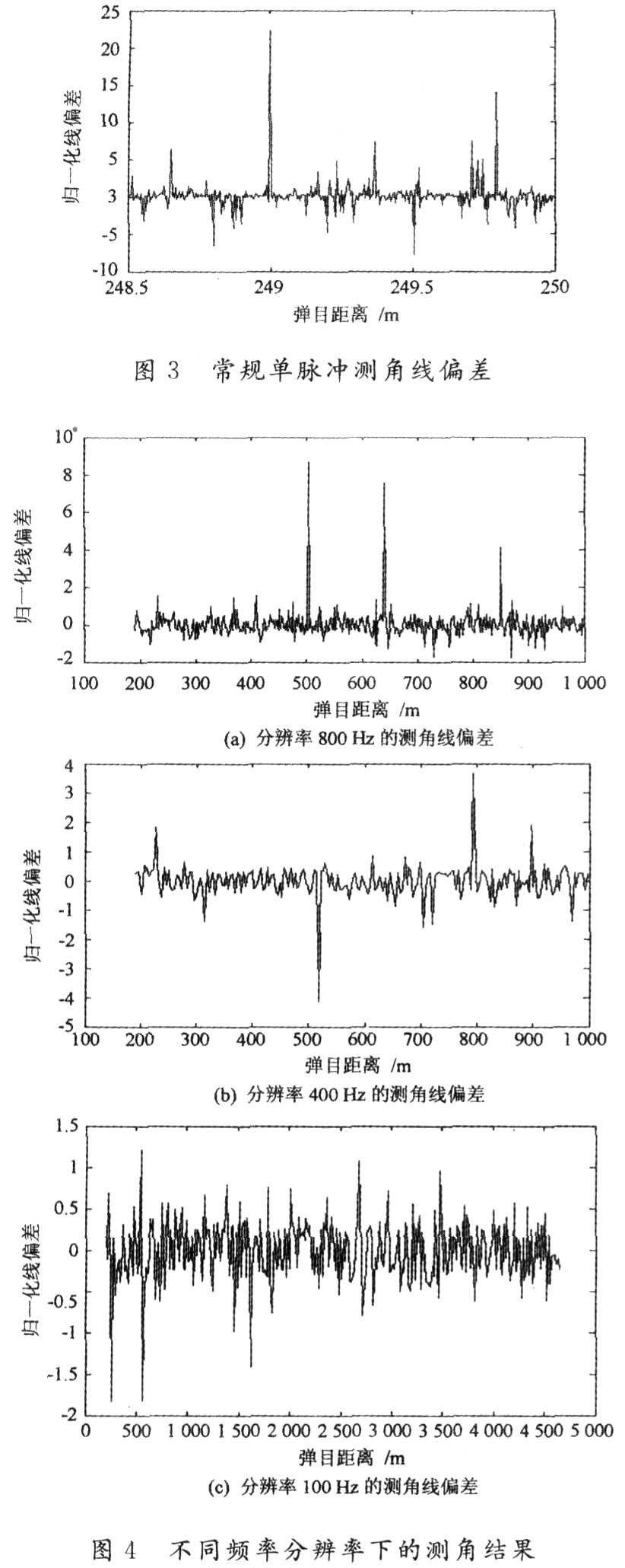
In order to verify the effect of high-resolution angle measurement in the frequency domain, Figures 3 and 4 show the angle measurement results of conventional single-pulse angle measurement and different frequency resolutions. The angle measurement result is expressed by the normalized line deviation. It can be seen that the angle measurement error of the conventional single pulse is relatively large. Angle measurement results with resolutions of 800 Hz, 400 Hz, and 100 Hz are shown in Figure 4. It can be seen that the angle measurement accuracy is greatly improved, and the higher the resolution, the higher the angle measurement accuracy.

4 Conclusion The high-frequency PD system terminal guidance radar has a wide range of applications in air defense systems. Improving its angular tracking accuracy is a key technology that needs to be solved urgently. Based on the analysis of the principle of high resolution in the frequency domain and the principle of monopulse angle measurement, this paper proposes a high resolution angle measurement algorithm in the frequency domain. This method is simple to implement and suitable for engineering applications. Simulation results show that the algorithm can effectively improve the system's angle tracking accuracy, and the higher the resolution, the higher the angle measurement accuracy.
Copper Wire Lights,Copper Fairy Lights,Copper Wire Fairy Lights,Wire Fairy Lights
DONGGUAN JIANXING LIGHTING ELECTRIC APPLIANCES CO., LTD , https://www.rslightstring.com