0 Preface
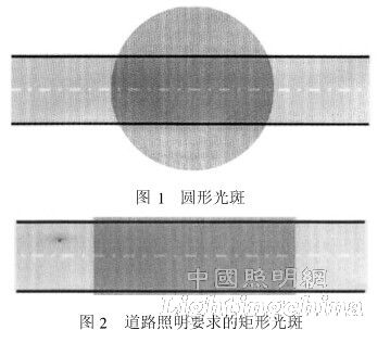
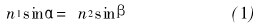
The LED light source has not been used as the illumination source for practical applications, but it has shown great advantages in the actual lighting project. The light source structure is compact, the overall luminous efficiency is high, and the lighting design is more flexible, but the LED light source is not easy to realize. . Most of the existing LED light sources have a circular light source with an exit angle of 110?~120?. If there is no light distribution, a large circular spot will be formed on the road surface, as shown in Figure 1 [1]. In order to effectively utilize the light of the LED, it is hoped that the road lighting fixture should distribute the light emitted by the light source reasonably in space, and finally form a rectangular spot with uniform illumination on the road surface, as shown in FIG. 2 . For high-power street lamps, the light source part mainly uses a single low-power LED array and a high-power integrated package LED light source. The former lamp design is limited by the number and arrangement of light sources, and the industry has accumulated certain lighting design experience, while the latter light The color consistency is easy to control, the luminaire assembly is simple, but the illuminating surface is large, and there is no design experience to rely on.
In the design of street lamps, the angle of change of the light source is limited, and the design of small exit angles cannot consider the light of large angle sources. That is, the road width limits the size of the lateral exit angle, and it is not easy to fully utilize in the horizontal scale. Light source energy [2], which poses a problem for the design of asymmetric free-form surface lenses, that is, the light should be pulled apart in the length direction of the road surface, so that the light shape has sufficient length, and the light is compressed in the width direction of the road surface, so that the LED The emitted light is concentrated in a rectangular area along the length of the road.
At present, some scholars use a free-form lens to design a street light distribution of a single LED light source, and there is less research on the light distribution of a high-power integrated package light source. Ding Yi et al. [3] constructed a first-order partial differential equation based on the topological correspondence between source energy and target surface energy, and then solved the surface data of the lens, but the curve fitting will be distorted during modeling, and the positive polygon illumination surface is obtained. , not the rectangle required in street lighting. Wang Hong et al. [4] also designed a free-form surface mirror based on energy conservation, dividing the light source and the target surface energy grid, but it also produced the problem of curve fitting distortion during modeling. This paper source
The high-power integrated package light source is used to design a free-form surface lens based on energy conservation, and the corresponding relationship between the light energy of the outer region of the road and the energy of the light source is constructed. Only the lens surface of this part is designed, and the quadratic curve is used as the busbar of the lamp lens. The point construction curve, according to the nature of the light source, the illumination requirements of the illumination surface and the illumination range, the orthogonal parameters are used to analyze the relevant parameters of the lens bus, and finally the optical free-form surface lens required for rectangular spot illumination is obtained.
1 lens curve slope equation
In the following discussion, the direction of the x-direction is defined as the direction of the road surface (ie, the direction along which the road vehicle travels), and the y-direction is the direction of the road width (ie, perpendicular to the direction of travel of the vehicle).
There are two common free-form surface design methods: numerical optimization and direct method. The numerical optimization method proposes an optimization function with several variable parameters, which requires the designer to have rich experience. Because it is repeated and optimized many times, the design process is long. The initial condition using the direct method is to know the illuminating properties of the light source and the illumination distribution on the intended illumination target surface. By adding a free-form lens, the light distribution of the light source is matched with the light distribution of the illumination target surface [4]. For the light distribution of the matching light source and the light distribution of the illumination surface, the optimization equation of the lens busbar is proposed in this paper, and the equation is used to construct the lens surface in the subsequent design.
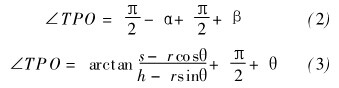
As shown in Fig. 3, the light source o is located at the origin of the rectangular coordinate, the length of the illumination road surface is s, the illumination height is h, and the angle between the light exit angle and the horizontal plane is θ, simplifying the design, and the lens is not refracted on the first refractive surface. The light is refracted only through the p-point of the second refractive surface of the lens. According to Snell's law, it can be expressed as
Where: n1 is the refractive index of the lens; n2 is the refractive index of air; α and β are the incident and exit angles of the light, respectively.
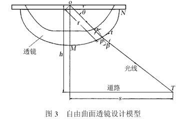
According to Figure 3, the following relationship can be derived:
The simultaneous (2) and the formula (3), the solution of β, the substitution of (1), available

From Figure 3, the tilt angle of p point is obtained.  for
for
The slope of point P is k = tan is 11, which is available.

It can be known from equation (6) that the angle θ between the exit angle of the beam and the horizontal plane is known, and the illumination spot width of the road surface is required to be s and the illumination height is h, and r is set, that is, the distance of the lens p point from the center o point of the LED light source. , the slope of the curve of the lens curve at point p can be determined.
2 free-form surface lens design
Now given integrated high-power LED light source, the power is 50W, the luminous surface diameter is 20mm, the luminous flux is 4200~4600lm, and the exit angle is 120°.
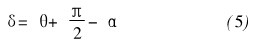
No lens is added, the light source is modeled in Light Tools, the receiving surface is set to a height of 10m, and the light source diameter is set to 20mm. Considering the luminous flux loss of the LED, the initial luminous flux of the light source is set to 4200lm, and the number of light is set to 3 million. The light source was simulated and analyzed. Figure 4 shows the simulation of the light source, and Figure 5 shows the simulation of the road illumination distribution of the LED light source.
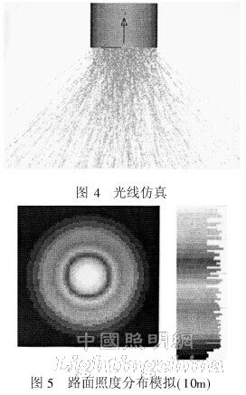
In the urban road lighting design standard, the average illuminance for the secondary road surface is 10~15lx, and if it is cement concrete pavement, the average illuminance value can be reduced by about 30% [5].
In order to meet the uniformity requirements of national lighting standards, in the past, the luminaires usually increased the output power, so that the secondary illuminance of the surrounding dark spots is not less than 2. 4 lx, and the light distribution length of the secondary dry road lamps requires an illumination path width of 10 m. The length is 32~50m. Figure 5 is analyzed, and the y-edge illuminance is analyzed in an area of ​​about 2. 5lx. In this illuminance area, the shape is a circular spot having a diameter of 28 m, the edge illuminance is 2.55 lx, the maximum illuminance value is 17.65 lx, and the average illuminance is 5. 02 lx. If there is no optical system, the illumination spot is circular, and cannot Rectangular illumination that meets the standard requirements.