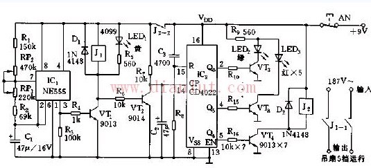
As shown in the figure, the ceiling fan low voltage start control circuit. The controller is composed of a multivibrator, a counter, a relay control circuit and the like.
The oscillation frequency of the multivibrator consisting of IC1 (555) and R1, W1, W2, R2, C1 is f=1.44/(R1+2Rw1+Rw2+2R2)C1, and its frequency and duty ratio can be adjusted. W1, W2 to change. When the 5553 pin outputs a high level, BG1 is turned on, the relay J1 is pulled in, and the contact J1-1 is closed, thereby controlling the operation of the fan. At the same time, BG2 is cut off, and a high level is input to the CP terminal of IC2.
IC2 (CD4022) is an 11-ary counter/pulse splitter. Under the action of CP pulse, Q1~Q5; the high-level appears in turn, and the LEDs LED3~LED7 emit red light sequentially (LED4~LED7 and BG4~ in the figure) BG7 is not drawn). When the terminal level of the Q6 is out, the BG9 is turned on, the relay J2 is pulled in, the contact J2-2 is disconnected, and the IC1 oscillator is stopped due to no power, indicating that the start of the round is completed. LED3~LED7 respectively show the number of starts in one round of experiments. LED2 (green) is lit, indicating the start of the start of the experiment.
SHENZHEN CHONDEKUAI TECHNOLOGY CO.LTD , https://www.szfourinone.com