This paper explores the application of PWM (Pulse Width Modulation) control technology in a single-phase bridge inverter circuit. The study begins by thoroughly explaining the fundamental principles of PWM control, which is essential for understanding how it can be used to shape and regulate output waveforms. A brief overview of the working mechanism of a single-phase bridge inverter is provided, followed by an in-depth analysis of how PWM control is applied within this configuration. Simulation results are then used to validate the theoretical findings, demonstrating the effectiveness of the approach.
1. Introduction
In the field of power electronics, inverter circuits play a crucial role, and PWM control technology lies at the heart of their operation. The challenge of effectively integrating PWM into inverter circuits has long been a key issue for researchers and engineers. This paper addresses this challenge by first explaining the basic principles of PWM control. It then delves into the implementation methods of both unipolar and bipolar SPWM (Sinusoidal Pulse Width Modulation). Finally, it combines these techniques with a single-phase bridge inverter circuit, analyzing and applying them in practice. The successful integration of PWM control into the inverter circuit is confirmed through simulation experiments, providing strong support for its practical use.
2. The Basic Principle and Implementation Method of PWM Control Technology
2.1 Introduction to the Basic Principles of PWM Control Technology
According to signal and system theory, pulses with the same impulse but different shapes produce the same effect when applied to a system with inertia. Figures 1(a), (b), and (c) show three different pulse shapes—rectangular, triangular, and sinusoidal. Although they appear different, their areas are equal. When applied to a first-order inertial system, their outputs are identical. This principle, known as the area equivalence principle, forms the foundation of PWM control technology.
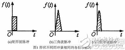
(a) Rectangular wave pulse (b) Triangle wave pulse (c) Sine half-wave pulse
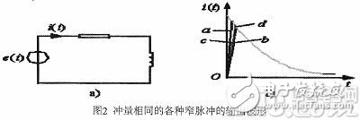
When these waveforms are applied to a first-order inertial link, the resulting output current i(t) is shown in Figure 2(a) and (b). While the rising portion of i(t) may differ slightly, the falling portion remains consistent. As the pulse becomes narrower, the differences between the waveforms become negligible. This principle underpins the design and implementation of PWM control systems.
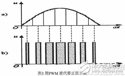
By dividing a sine half-wave into N equal parts and replacing each segment with a rectangular pulse, we can achieve a waveform that is equivalent in area to the original sine wave. This method is the basis for generating PWM signals, which are widely used in power electronics for efficient voltage regulation and waveform shaping.
2.2 Implementation of Unipolar and Bipolar SPWM
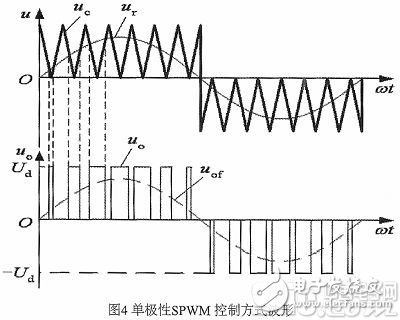
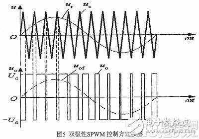
To generate a desired PWM waveform, a modulated signal is compared with a carrier wave. Typically, an isosceles triangle wave is used as the carrier due to its symmetry and linear characteristics. When the modulating signal intersects with the carrier, the switching devices are turned on or off, creating pulses whose widths are proportional to the amplitude of the signal. This process is the core of PWM control. When the modulating signal is a sine wave, the result is SPWM. In unipolar SPWM, the carrier wave operates only in one polarity during a half-cycle, resulting in a waveform that remains in one polarity. In contrast, bipolar SPWM uses a carrier that alternates between positive and negative polarities, producing a bi-directional output waveform.
As shown in Figure 5, in bipolar SPWM, the output waveform contains two levels, ±Ud, without a zero level. This mode is particularly useful in applications where full waveform control is required, such as in AC motor drives and power supplies.
3. Application of PWM Control Technology in Inverter Circuits
3.1 Working Principle of Single-Phase Bridge Inverter Circuit
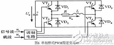
Figure 6 illustrates a single-phase bridge inverter using IGBTs as switching devices, connected to a resistive load. The unipolar SPWM control method, as shown in Figure 4, is used to regulate the output. In this configuration, VT1 and VT2 operate complementarily, as do VT3 and VT4. During the positive half-cycle of Uo, VT1 is on while VT2 is off, and VT3 and VT4 alternate. Due to the inductive nature of the load, the current lags behind the voltage, leading to both positive and negative current intervals. When VT1 and VT4 are on, the load voltage is Ud; when VT4 turns off, the current continues through VT1 and VD3, resulting in a zero voltage state. This cycle repeats, allowing the inverter to produce both Ud and 0 levels.
3.2 Application of PWM Control Technology in Inverter Circuits
The control of VT3 and VT4 can be implemented using either the unipolar SPWM method from Figure 4 or the bipolar control method from Figure 5. For example, if the modulation signal Ur is a sine wave, the carrier Uc will be a positive triangle wave in the positive half-cycle and a negative triangle wave in the negative half-cycle. The IGBTs are switched on and off at the intersection points of Ur and Uc. During the positive half-cycle of Ur, VT1 remains on while VT2 is off. When Ur exceeds Uc, VT4 turns on and VT2 turns off, resulting in a Ud output. When Ur is less than Uc, VT3 turns on and VT4 turns off, resulting in a zero output. The fundamental component of the output voltage is represented by the dotted line Uof. The difference between VT3 and VT4 lies in the gate drive levels—one being unipolar and the other bipolar.
4. Simulation Verification
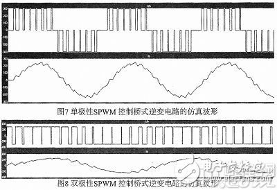
To verify the correctness of the PWM control application in the single-phase bridge inverter, simulations were conducted. Figures 7 and 8 show the results. In Figure 7, the upper waveform represents the simulated output voltage across the load, while the lower waveform shows the load current. These results match the theoretical analysis from Figure 4. Similarly, Figure 8 presents the simulation of a bipolar SPWM-controlled inverter, where the output voltage and current waveforms align with the expected behavior from Figure 5. These simulations confirm the validity of the theoretical model and the effectiveness of PWM control in real-world applications.
5. Conclusion
Through the detailed analysis presented in this paper, it is evident that the integration of PWM control technology into inverter circuits not only enhances stability and reliability but also allows for easy adjustment of the duty cycle, enabling precise control over the output voltage. This flexibility makes PWM an essential tool in various industrial applications, paving the way for more efficient and versatile power conversion systems.
This battery is for replacing lead-acid battery, it has the standard appearance and size as well as capacity, but longer cycle life and high energy and good charge and discharge performance.
Capacity:100AH/150AH/180AH/200AH/250AH.
Voltage:12.8V, cycle life is more than 2000 times, also can customize the capacity.
12V Rechargeable Lithium Battery,Lithium Polymer Battery,Rechargeable Lithium Ion Batteries,LFP Battery,24 volt Battery12v 200Ah Powerful Bank,Home Storage Rechargeable Battery
Enershare Tech Company Limited , https://www.enersharepower.com