0 Preface
This article refers to the address: http://
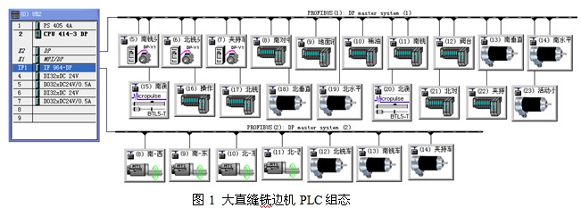
The large straight seam milling machine developed by our company is one of the key equipments in the large-diameter straight seam welded pipe production line (JCOE) in the oil and gas pipeline manufacturing industry. This equipment is the first domestic independent research and development. The electrical control system uses Siemens two PROFIBUS bus communication, which consists of 28 master-slave communication stations to realize global digital real-time monitoring communication. In the system configuration, Siemens CPU414-3DP is selected as the master station, ET200S remote I/O, 70 inverter, TR encoder, MTS displacement sensor, proportional servo valve, Balluff micropulse displacement sensor as slave stations (see Figure 1 for details). Large straight seam milling machine PLC configuration), Siemens touch screen MP377 setting and display. All speed, displacement, safety protection and fault points in the system must be monitored and alarmed on the screen in real time. Due to the large number of communication ports and long distances, there are many program modules (see Figure 2 for the large straight seam milling machine PLC program block). The automation level is high and the control is very difficult.

1 70 PROFIBUS-DP communication of the inverter
1.1 The communication mode is set to PPO 4, this mode is 0 PKW/6 PZD, the input and output are all 6 PZD, under the setting of P60=7, set P53=3, allow CBP2 (PROFIBUS) operation, P918.1 setting The PROFIBUS address of the drive.
1.2 Set the PZD of the first and second inputs to the control word of the PLC to the inverter, set the PZD of the first and second outputs to the status word of the inverter to the PLC, and set the third to feedback the inverter to the PLC. The percentage value of the actual output frequency, the fourth is the percentage of the actual output current that the inverter feeds back to the PLC.
1.3 The first PZD of the PLC to the inverter is stored in the K3001 word in the inverter. When it is set to P554=3100, P571=3101, P572=3102, the bit 3100 of K3001 controls the start and stop of the inverter, 3101 In order to control the forward rotation, 3102 controls the reversal.
1.4 PLC to the second PZD of the inverter is stored in the K3002 word in the inverter. If P443=K3002, then the whole word K3002 is the main control word given by the PLC to the inverter, and the second word sent by the PLC. The size is 0 to 16384 (corresponding to 0 to 100% of the inverter output). When it is 8192, the inverter output frequency is 25Hz.
1.5 Program: (Create DB17, call SFC14, SFC15, the address of the inverter is 512 both W#16#200)
1.5.1 Reading data
CALL "DPRD_DAT"
LADDR :=W#16#200
RET_VAL:=MW200
RECORD :=P#DB17.DBX0.0 BYTE 12 (Read 12 BYTE)
NOP 0
1.5.2 Sending data
CALL “DPWR_DATâ€
LADDR :=W#16#200
RECORD :=P#DB17.DBX12.0 BYTE 12 (write 12 BYTE)
RET_VAL:=MW210
NOP 0
1.5.3 L “DB17â€.DBW0
T “MW20â€
NOP 0
1.5.4 L “DB17â€.DBW2
T "MW22"
NOP 0
Then: DB17.DBX 13.0 controls start and stop;
DB17.DBX 13.1 controls forward rotation;
DB17.DBX 13.2 control inversion;
M21.1 inverter READY;
M21.3 Inverter FAULT.
2 Encoder PROFIBUS-DP communication
2.1 Read the encoder value.
LP##Peripherieaddr
TAK
LAR1
L PID [AR1, P#0.0]
T #actual_C1_DI
2.2 Data correction, plus correction value (offset, generally negative).
L #actual_C1_DI
L #offset
+D
T #actual_C2_DI
NOP 0
2.3 Convert and convert to actual position, data type conversion, multiply by conversion factor to get the actual position.
A (
L #actual_C2_DI
DTR
T #actual_Pos_R
SET
SAVE
CLR
A BR
)
JNB _006
L #actual_Pos_R
L #multipliactor
*R
T #actual_position
_006: NOP 0
3 PROFIBUS-DP communication of the displacement sensor
3.1 Encoder data acquisition 1, PID 257 (L) / PID 258 (M), MB 103 (L) / MB 102 (M).
A (
L PIB 257
T MB 103
SET
SAVE
CLR
A BR
)
JNB _001
L PIB 258
T MB 102
_001: NOP 0
3.2 Encoder data acquisition 2,0 / PID259(H), MB100(HH)/ MB101(H).
A (
L PIB 259
T MB 101
SET
SAVE
CLR
A BR
)
JNB _002
L 0
T MB 100
_002: NOP 0
3.3 Read the status bit parameter and send the status bit to MB80.
L PIB 256
T MB 80
NOP 0
3.4 Correction result, MD100 is the encoder sampling data, MD104 is the encoder zero correction value, MD108 is the modified result, and participates in the control; MD104 is set on the HMI (Human Machine Interface).
L MD 100
L MD 104
+R
T MD 108
NOP 0
4 When the ET200S is used as a remote I/O substation, its PROFIBUS-DP communication is relatively simple. Simply set the PROFIBUS-DP address on the interface module, which will not be detailed here.
5 PROFIBUS-DP communication should pay attention to the problem
5.1 The connection between the bus connector and the bus cable should be reliable. The shield must be pressed firmly and firmly. The scattered wires should be bundled and cannot be in contact with the chip on the bus connector.
5.2 The DC24V GND on all master and slave stations should be connected.
5.3 Keep the bus cable as far as possible from the power cable to prevent electromagnetic interference.
5.4 The wiring of 132KW motor and inverter should be shielded cable as much as possible. The shield laminate is connected in the electrical box and the motor side is suspended.
5.5 The PE wire is reliably connected to all equipment with the thickest possible grounding wire.
5.6 The grounding copper bar in the electrical box should be reliably connected to the grounding copper bar in the plant.
6 Conclusion
Since many non-Siemens bus products are used in this control system, although they all support the PROFIBUS protocol, there are still many different places in the communication software. We need to repeatedly understand, digest and experiment repeatedly. After two years of our work. A lot of work, the device has been debugged and delivered to the user, the effect is good.
Tin Zinc Alloy Wire is a kind of electronic welding material speciallized for metal spraying of the end face of metalized film capacitor.The capacitors have been widely used in high-speed rail,automobiles,new energy and aerospace fields.
Application Fields: Metal spraying material is a kind of electronic welding material specialized for metal spraying of the end face of metalized film capacitor.
Tin Zinc Alloy Wire
Tin Zinc Alloy Wire,Zinc Alloy Wire,Tin Zinc Alloy Soldering Wire,Alloy Wire
Shaoxing Tianlong Tin Materials Co.,Ltd. , https://www.tianlongspray.com