This article provides an in-depth explanation of common mode chokes used in signal lines. These components play a crucial role in reducing noise and improving signal integrity, especially in high-speed differential communication systems.
1. **Signal Line with Common Mode Choke: Offset Improvement Function**
A common mode choke is typically used in signal lines to suppress common-mode noise, which can interfere with the accurate transmission of signals. As a type of transformer-based component, it helps maintain balance in differential signaling. In ideal conditions, the two signal lines should be perfectly matched, but manufacturing variances or imbalances can lead to timing differences between them. This imbalance causes signal skew, where one signal arrives before the other, resulting in distortion or reduced performance.
To illustrate this, Figure 1 shows the offset that occurs when the signal lines are not balanced. By placing a common mode choke at the appropriate point, this offset can be significantly reduced. Figure 2 presents the structure of how a common mode choke improves signal alignment. The choke works by generating an opposing electromotive force when the rise and fall times of the two lines are unbalanced, helping to equalize their timing and reduce skew.
Figure 3 demonstrates the effect of a common mode choke on signal integrity. When the lines have different lengths, the rise and fall times of DOUT+ and DOUT- are not synchronized. However, when a common mode choke is added, the timing becomes more consistent, and the sum of the two signals remains stable, confirming the improvement in signal balance.
2. **Equivalent Circuit Diagram of a Common Mode Choke**
The equivalent circuit of a common mode choke resembles that of a transformer, with two windings connected in series. On the diagram, black dots are often marked on the coils. Many people wonder if these dots indicate a starting point or some physical feature, but in reality, they represent the direction of the magnetic coupling between the two windings.
In a properly designed common mode choke, the magnetic flux from each winding reinforces each other for common-mode signals while canceling out for differential-mode signals. If the winding directions are reversed, as shown in Figure 5, the choke may no longer function correctly, leading to a loss of its filtering capabilities.
The black dot is also used in traditional transformer diagrams to indicate polarity. It shows the relative voltage phase between the primary and secondary windings. Understanding the placement of these dots is essential for proper installation and performance of the common mode choke in a circuit.
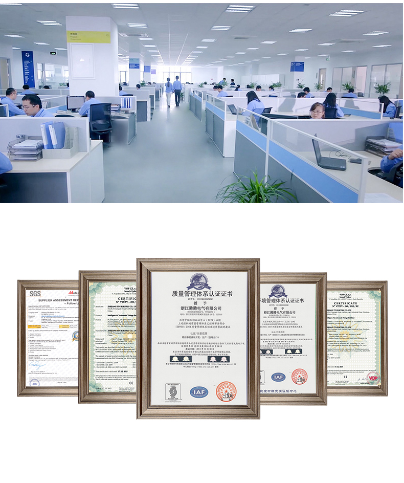
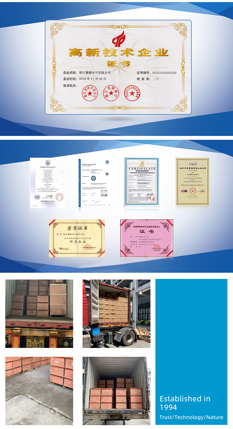
Relay Control Voltage Regulator
PC-TM series Relay Control Voltage Stabilizer has the low energy consumption,the over voltage protection,the low voltage protection,the over-current protection,the over-loading protection,the over-temperature protection and so on.It boasts for many kinds of protections,the collection energy conservation and the environmental protection ect.This is a brand-new concept product which possess many new technologies!This series products simultaneously ha applied for many technical monopolies
We already applied many kinds of this products patent, and the technical patent NO: 200720036394.1 and Appearance paten NO: 200730025909.3
2. Use for equipment:
Computer
Test equipment
Light system
Safe alarm system
Ray equipment
Medical equipment
Copy machine
Stereo equipment
Numerical control machine tools
Industrial automation equipment
Color and drying equipment
Test equipment
Hi-Fi equipment


Relay Control Voltage Regulator ,Voltage Regulator For Ac,3000Va Voltage Regulator,Wall Mount Voltage Stabilzier
zhejiang ttn electric co.,ltd , https://www.ttnpower.com