The integrated video filter was very expensive at the beginning, and it was a very high-performance component for video broadcasting applications, and it gradually evolved into a cost-sensitive consumer electronics solution for set-top boxes. The first mainstream integrated video filter was introduced in the early 1990s, first in direct broadcast satellite set-top boxes and cable set-top boxes. So, what is the role of the video filter? First, it can be used as a reconstruction filter after the digital-to-analog converter on the output of the video processor; the second is used as a video processor input in the set-top box and DVD device. Anti-aliasing filter.
This article refers to the address: http://
In the past, the choice of video filter was very easy. Just consider the number of outputs: general filter for composite video (CVBS), two filters for S-video, and three-component video output for DVD players. For Y, Pb, and Pr, these have become standard on the back of video equipment. As a result, video device users and designers must consider the total number of analog outputs up to six (ie CVBS, S-video (Y, C), component video (Y, Pb, Pr)).
However, with the advent of higher-definition video and consumer acceptance as costs continue to fall, the situation has changed. The numbers "i" or "p" appear after the numbers 480, 720, and 1080 (and other non-US standard video). This strange number/letter combination has also become one of the growing terminology in the video world. So what do they mean? The number/letter combination of 480i, 1080p, etc. refers to the number of lines of video scanning, and whether it is interlaced (i) or progressive (p). Interlaced means that each row is alternately scanned for display, and progressively, each row is sequentially scanned for display.
Interlaced scanning is a technology that has been passed down from the old CRT screen design. The purpose is to make the phosphors on the glass panel emit light, let the top fade out, and the bottom is replaced, so that the phosphor layer will not be formed before the image is completed. Blanking. Phosphor lighting time must be long so as not to affect the next frame of image. Line by line is the sequential illumination of pixels. This scanning method has higher spatial resolution and better visual effect. Obviously, for consumers who just want to watch videos and don't want to be a video engineering expert, it's all too complicated. Therefore, in order to facilitate understanding and at the same time facilitate sales, it is necessary to create a set of short and easy-to-understand terms. Thus, under the term "sharpness", a variety of digital/letter combination categories are formed, which are mainly used to describe the detail performance of an image: the higher the definition, the better the image quality, because more lines mean more. More pixels make the color and detail of the image more vivid and vivid.
The classification of signals and the classification of sharpness categories can be written into a thick monograph, and it may become a hot topic for video engineers for a long time. In view of the discussion of the actual video filter purpose, the rough division is as follows: 480p is standard definition (SD), 480p is enhanced definition (ED), and 720p and 1080i are high definition (HD). For convenience, only the US standards are discussed here. In addition, many video equipment vendors are beginning to loosen when using the term high definition (HD). In order to be more precise, the video industry associations have proposed terms such as HD ready, HD ready 1080p and Full HD, but this has been a mixed success and may even cause more confusion. To this end, the video filter manufacturer decided to use the terms SD, ED, HD, and 1080p HD to classify the filter based on the cutoff frequency of the filter (passband for the low-pass filter): the SD filter cutoff frequency is Around 8MHz, ED is around 20 MHz, HD is around 30MHz, and 1080p cutoff frequency is between 65 and 70MHz. It is very straightforward to use the cutoff frequency to classify.
So, what is the relationship between all these video definitions and the choice of video filters? Understanding these new definition standards actually reveals that the choice of video filters must take into account two factors: the designer must consider both the number of channels and Sharpness. In addition, there are two ways to implement integrated circuit filtering: one is to use a combination of filter ICs, and the other is to use a single filter IC that can handle all the different channels and resolutions. How should the designer decide? One way is to find a variety of filters that meet the requirements. For example, Fairchild Semiconductor is able to offer a wide range of filter combinations to meet different requirements.
When starting the selection, you can refer to the example diagram in this article. Figure 1 shows Fairchild's filter for different channel/sharpness combinations. One axis in the figure represents the number of channels, and the other axis represents the type of sharpness, which helps designers to select the appropriate filter more easily. Filter selection is just the beginning, and there are other issues that need to be addressed. But this is a good start.
As long as the number and clarity of channels are determined, designers should begin to consider other key factors in product selection, such as ESD protection, standby power requirements, voltage rail requirements, and package types, especially in the rapidly growing trend of mobile video applications. Device size is also critical.
As for ESD, set-top box manufacturers have standardized BAV99 protection diodes for discrete filtering. On the other hand, the integrated video filter not only eliminates a large number of discrete filter components, but also reduces the number of diodes used. For specific products, integrated filters are capable of providing ESD protection up to 12KV. ESD protection is indeed a noteworthy issue. In order to avoid damage to expensive TV core processing chips, designers should not bring unprotected video output products to market.
Another issue that has received increasing attention is the reduction in standby power consumption. Standby power is sometimes referred to as "vampire power," which has become a major environmental issue. For example, California has recently enacted regulations to reduce LCD TV standby power consumption, which requires such products to meet the Energy Star standard. Fairchild will provide filters with associated break modes to better meet ENERGY STAR requirements.
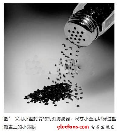
Packaging for mobile products such as WLCSP and MicroPak MLP is now also being used for video filters. For mobile applications, size is critical, so these small packages are especially useful. In fact, they are small enough to easily pass through the small mesh on the salt cap.
For video filters, designers should adhere to careful design principles. For example, you should ensure that the wires are as short as possible and close to the actual output ports to reduce board parasitics. This concept is explained in more detail in Fairchild's "Application Note AV-6041: PCB Layout Considerations for Video Filters/Drivers".
As long as you know which products are available and which are important considerations, it has become quite easy to choose the right filter. Fairchild Semiconductor is always happy to provide engineers with all the assistance they need. After all, helping customers succeed means the success of video filter vendors themselves, and video engineers love to talk about video. Fairchild is pleased to provide you with timely and detailed support as you plan your next design.
IP66 / IP67 waterproof d-sub connectors-Designed for IP Performance
ANTENK has developed IP66 / IP67 waterproof d-sub connectors that utilize a proprietary sealing technology, which maintains the same physical size and footprint as standard d-sub products.
Antenk's line of Waterproof d-sub connectors utilize an innovative sealing technology eliminating the need to redesign enclosures and PC boards when implementing IP67 design upgrades.These connectors are designed for applications that require protection from heavy spray or are exposed to short-term submersion. Connectors are available in vertical and right angle board mount types as well as solder cup for panel mount cable applications. Standard D-Subs are available in 9 pin , 15 pin , and 25 pin positions, and high density D-Subs are available in 15 pin, 26 pin, and 44 pin positions
Applications of Antenk waterproof d-sub connectors:
Hand held computers, scanners, and printers that are used outdoors
Remote sensors, gauges, and data loggers that are used outdoors
Industrial and Medical equipment that is routinely subject to wash down
Transmitters and emergency beacons that are subject to temporary submersion
Gas, Electric, and Water metering systems that have embedded Smart Grid electronics
Portable electric generation equipment (Gen Sets)
Consumer and Commercial boating electronics (Radios, Scanners, Radar, DC Power Ports)
IP67 D-SUB | WATERPROOF CONNECTORS FEATURES & BENEFITS
Signal / Low Power in 6 standard size
(Standard: 9 pin, 15 pin, 25 pin | High Density: 15 pin, 26 pin,44 pin)
Combo-D / High Power in a variety of configurations:
(3W3, 5W5, 7W2, 9W4, 11W1, 13W3, 13W6, 17W2, 21W1, 21WA4)
Solder Cup, Vertical Mount & Right Angle Board Mount Options
High Reliability Screw machined contacts
3 amp / 5 amp / 20 amp / 40 amp Power Options
-65°C to +105°C Operating Temperature Range
Range of Antenk waterproof d-sub connectors
solder cup, stamped & formed contact D-sub waterproof
solder cup,machined contacts D-sub waterproof
vertical mount D-sub waterproof
right angle D-sub waterproof
IP67 rated Combo power D-sub waterproof
D-Sub adapters, couplers, and splitters
Waterproof D-Sub Connector & D-SUB Adapter
solder cup Waterproof D-Sub Connector,vertical mount Waterproof D-Sub Connector, right angle Waterproof D-Sub Connector,Combo power D-sub Waterproof D-Sub Connector,Waterproof D-Sub Connector,D-SUB Adapter,IP66/ IP67/IP68 Rated D-sub connectors
ShenZhen Antenk Electronics Co,Ltd , https://www.antenk.com