Abstract: With the increasing number of cars in modern society, the research on car collision avoidance technology has become the key to ensuring people's life safety and improving the transportation industry. The project aims to study a car collision avoidance system to ensure that there is no collision accident or reduced road capacity in the normal operation of the system. The system utilizes the linear frequency modulation characteristics of the LFMCW and the principle of the Doppler effect to measure both the distance between the two vehicles and the relative motion, and combines the measured values ​​of the two to achieve an effective collision avoidance function. The related parameters determination, specific implementation method and principle analysis of LFMCW radar used in automobile anti-collision system are mainly discussed.
Key words: automobile anti-collision; LFMCW; Doppler effect; relative motion
With the development of the national economy, the number of cars is increasing, and the transportation of automobiles is becoming more and more busy, but at the same time, traffic accidents are not uncommon. Therefore, the development of automobile anti-collision technology is of great significance to improve the level of intelligent car. In order to avoid collision, the car must measure the distance of the obstacle in front with a certain equipment and quickly feedback it to the car to avoid the alarm or automatically perform a certain preset operation such as emergency braking in case of emergency. Traffic accidents caused by driver fatigue, neglect, and misjudgment. This article focuses on the criticality of collision avoidance technology in vehicle ranging technology. From the perspective of measuring distance and relative speed, effective anti-collision effect is achieved.
1 Research and setting of safety distance
1.1 Parameter Determination The so-called safe driving distance refers to the distance between the two workshops before and after driving in the same lane (the distance between the rear and front vehicles), keeping no rear-end collisions and no roads. The appropriate distance of capacity. Formula for calculating the safe distance:
d*=η/(vt+v2/254φ) (1)
It can be known that the safe driving distance is required, and the parameters to be determined include the vehicle speed v, the reaction time t, the adhesion coefficient φ between the tire and the road, and the system adjustment coefficient η.
1) The speed of the car v
Real-time values ​​can be measured using the vehicle speed sensor of the car collision avoidance system.
2) Reaction time t
According to the relevant experts, in general, the response time of most drivers is between 0.30 and 1100 s, plus the time when the brake system acts. The total reaction time is 1.30~1.98. Between s, the value is 1.30 ~ 1.98 s.
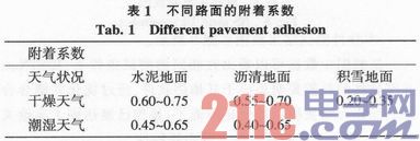
3) Tire and road adhesion coefficient φ
The adhesion coefficients of different road surfaces are shown in Table 1.
This article refers to the address: http://
4) System adjustment coefficient η
In order to be safe, the driver should set the adjustment factor η according to his own different requirements for safety effects. If it is conservative, choose η value is larger. The value of η ranges from 1.05 to 1.10, usually 1.10.
5) Safety spacing d0
When the braking of the two cars is stopped, a certain distance d0 should be maintained to ensure safety. Whether the d0 selection is reasonable or not has a certain impact on the false alarm rate of the system. The ideal situation can be a minimum of 0, but the data at home and abroad is generally 2 to 5 m, which is 5 m for safety reasons.
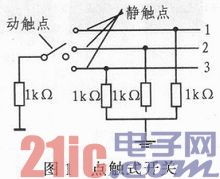
1.2 System model realization process Given a car collision avoidance system, according to the influencing factors and value range of each parameter, set the corresponding parameters: t = 1.8 s; η = 1.10; d0 = 5 m. In the driving process, the adhesion coefficient φ between the tire and the road is set with reference to the data of Table 1 according to the type of the road surface. According to the calculation, when the speed is the same, the safe driving distance obtained by different road conditions is different, and the greater the speed, the larger the difference of the safe driving distance is. Therefore, it is decided to install a road surface selection switch, which is realized by a touch switch. The driver selects the adhesion coefficient subjectively according to the weather condition, and then performs data processing to determine the safe driving distance under the adhesion coefficient. The switch selection is shown in Figure 1.
2 Doppler shift measurement
2.1 Extraction of Doppler information If the reflected signal comes from a relatively moving target, the reflected signal includes a Doppler shift fd caused by the relative motion of the target.
According to the Doppler principle, the relative motion speed of the target can be expressed by equation (1): ![]()
Where f0 is the center frequency of the transmitted wave and λ is the wavelength of the transmitted wave.
To take out the Doppler frequency from the received signal, a beat method is required, that is, the difference fd between f0 and fr is taken out.
The classic beat method uses coherent demodulation to multiply the received signal and the transmitted signal by a multiplier, and after passing through a low-pass filter, the desired difference frequency signal can be obtained.
2.2 Coherent detection principle Coherent detection is also called coherent demodulation, the purpose is to extract the modulated signal from the received signal. Assume that the transmitted signal and the received signal are respectively s(t)=Acosω0t (3)
r(t)=Bcos(ω0+ωd)t (4)
The general model of coherent demodulation is shown in Figure 2.
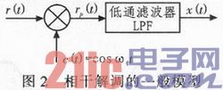
Multiplying the signal c(t) of the same frequency at the receiving end to obtain rp(t)=r(t)cosω0t
=[Bcos(ω0+ωd)t]*cosω0t
=B[cos(2ω0+ωd)t+cosωdt]/2 (5)
After passing through the low-pass filter, x(t)=Bcosωdt/2 (6)
x(t) is the beat signal of the received signal and the transmitted signal, and the Doppler shift is extracted.
3 LFMCW radar signal generation and reception
3.1 Generation of LFMCW radar signals
The basic composition block diagram of the LFMCW radar system is shown in Figure 3.
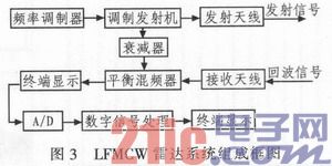
The LFMCW is a modulated RF signal generated by a VCO (Voltage Controlled Oscillator) under the action of a modulated signal. The frequency of the VCO output signal varies linearly with the amplitude of the modulated signal. A portion of the VCO output signal is amplified by the power amplifier and transmitted wirelessly, and another portion is applied to the mixer as a local oscillator signal of the mixer via a directional coupler. The transmitted signal is partially reflected if it encounters the target during the forward process, and the reflected signal is mixed by the receiving antenna and mixed with the local oscillator signal, and the intermediate frequency signal is output through the band pass filter, and the subsequent signal processing circuit can be obtained from the intermediate frequency signal. Extract information such as the distance and speed of the target.
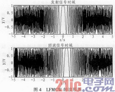
The waveform diagram of the LFMCW signal generated by using MATIAB programming is shown in Fig. 4. As can be seen from the figure, the transmitted signal is a LFMCW waveform whose frequency decreases linearly and then increases, and the echo signal is identical to the transmitted signal waveform, but there is a delay.
3.2 Clutter processing of LFMCW radar echo signal Coupling the transmitted signal and the echo signal to the mixer for mixing, outputting the intermediate frequency signal, combined with the actual consideration of various backgrounds (such as features, clouds and rain, etc.) Wave signals, radar target echo signals are often aliased in the background of interference clutter. Most clutter is distributed clutter, and there is internal motion with a wide spectrum. At this point, moving target detection (MTD) is required for the echo signal. The moving target detection of radar signals is to use the Doppler filter bank matched with the coherent echo pulse train to suppress various clutter, improve the power signal-to-noise ratio, and realize the coherent accumulation to enhance the radar detection in the clutter background. The technology of moving target ability. The essence is equivalent to the coherent accumulation process for different channels. The implementation method is to pass the echo signal through a group of Doppler filter banks for signal processing, and separate the moving target echo and the clutter. The simulation results of MTD processing are shown in Figure 5.
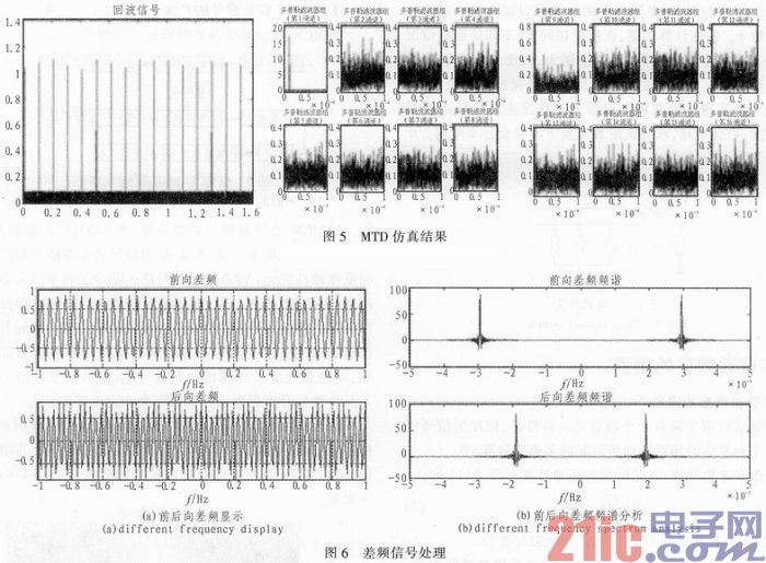
3.3 IF signal processing For the LFMCW signal generated in Figure 4, the comparison can only have a certain delay of the echo signal relative to the transmitted signal, even if there is Doppler shift, the forward and backward frequency of the IF signal The difference also has a relatively constant phase with respect to the change period. The rectangular window is used to intercept the constant phase and perform spectrum analysis. As shown in Fig. 6(a)(b), the forward direction can be obtained by processing. The frequency difference and the backward frequency difference, and then the distance and relative speed are obtained.
4 Ranging principle of LFMCW radar signal The carrier frequency of the FM continuous wave radar changes linearly during the modulation period. There are also many ways to change the linearity. Combined with the test demand analysis, this paper uses the LFMCW of the triangular wave modulation method to measure. From the perspective of relative motion, focusing on the reflected signal from a relatively moving target, the reflected signal frequency will also include a Doppler shift caused by the relative motion of the target, as shown in Figure 7.
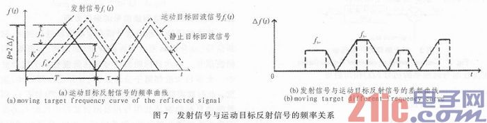
The transmitted signal can be expressed as:
Fl(t+)=fl+Kt (7)
Fl(t-)=fu-Kt (8)
Where K is the slope of the triangular wave.
The corresponding echo signal can be expressed as:
Fr(t+)=fl+K(t-Ï„)+fd (9)
Fr(t-)=fu-K(t-Ï„)+fd (10)
Thus, the difference frequency signal can be obtained as follows:
Fb+=|fr(t+)-fl(t+)|=KÏ„-fd (11)
Fb-=|fr(t-)-fl(t-)|=KÏ„+fd (12)
The two-type subtraction yields the Doppler shift fd: 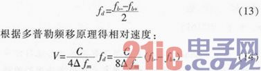
Combined with the solution formula of relative speed and the design idea and working principle of the collision avoidance system, it can be known that it is necessary to judge whether the two vehicles are close or far away, and only need to judge the symbol size of fb- and fb+. Through the above analysis, it can be known that finding the frequency difference of the LFMCW up-and-down frequency band and comparing the magnitude of the value becomes the key to achieve effective anti-collision processing.
5 Conclusion The design system focuses on measuring the relative motion of the two workshops. As long as it is judged whether the distance between the two vehicles meets the safety distance, the Doppler effect is used to determine whether the relative motion of the two workshops is close or far away. To achieve car collision avoidance, it is not necessary to measure the relative speed value in real time. This reduces a lot of unnecessary signal processing and calculations.
Uvc Light,T5 Uvc Lamp,T5 Uvc Tube,T5 Uvc Bulb
Changxing leboom lighting product CO.Ltd. , https://www.leboomuv.com