introduction
The CAN (Controller Area Network) bus is a serial data communication protocol developed by Bosch in Germany in the early 1980s to solve the data exchange between many control and test instruments in modern automobiles. Its short-frame data structure, non-destructive bus arbitration technology and flexible communication methods adapt to the real-time and reliability requirements of automobiles, and are favored by automobile manufacturers. With the development of automotive electronics technology, there are more and more ECUs (Electronic Control Units) on automobiles, such as electronically controlled fuel injection systems, anti-lock braking systems, anti-skid control systems, etc. Increasingly large, how to adopt a reasonable storage solution is the key to a large-capacity storage system such as a recorder. This paper elaborates on the overall structure and hardware circuit design of the mass storage system. Using "FPGA + MCU" as the storage controller, using LZW algorithm-based data compression technology, SDRAM as the cycle storage and cache, SD card as the final storage carrier. The experimental results show that the storage system can be well applied to the vehicle information recorder.
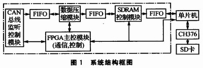
1 The overall structure design of the system is shown in Figure 1. The storage system mainly includes the following modules: FPGA main control module, CAN bus monitoring control module, data compression module, SDRAM control module and single-chip control CH376 module. This article mainly introduces the storage part, and the CAN bus monitor control module does not introduce it. In the figure, the parts in the dotted line are controlled by the FPGA. The back-end SD card is controlled by the MSP430 microcontroller, and the SD protocol chip uses CH376. The FPGA controls the CAN bus control chip and the CAN bus transceiver to acquire data from the bus, compress it through the data compression module, and store it in the SDRAM. Two storage modes are used here: one is to use the coverage of SDRAM storage for periodic storage, the specific storage period is determined by the compression ratio and SDRAM capacity; the other is direct storage, SDRAM as a cache. When direct storage is selected, the FPGA communicates with the MCU, and the data is sent to the MCU by the FIFO. The MCU controls the CH376 to store the data in the SD card (the storage time is determined by the SD card capacity).
This article refers to the address: http://
2 system hardware design
2.1 FPGA main control module FPGA selects Altera's Cyclone II series chip EP2C5T14418N, which has the characteristics of rich internal resources and fast speed. After power-on, the main control module enables the CAN bus monitor control module, data compression module, and SDRAM control module. If the cycle memory is selected, the MCU is not enabled; if direct storage is selected, the MCU is in a low power state. When the SDRAM has data, the FPGA sends the data to the MCU and controls the CH376 to work.
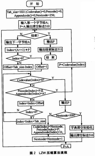
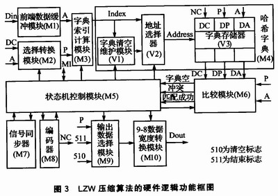
2.2 Data compression module The compression algorithm uses the LZW algorithm. The algorithm is a dictionary-based compression algorithm that dynamically builds a dictionary based on input data during data compression. Subsequent input data will be matched and searched in this dictionary, and the compression encoded output will be determined according to whether the search succeeds. The ingeniousness of the algorithm is that the dynamically created dictionary in the compression process does not need to be transmitted and stored together with the compressed data stream. However, when the data is decompressed, the dictionary can be re-established by compressing the data stream to complete the decompression. The flow of the LZW compression algorithm is shown in Figure 2. According to the process, the compression and decompression software is designed in C language to verify the correctness of the algorithm and hardware compression. The compression code is written in Verilog language, and the dictionary is built by using the internal RAM resources of the FPGA. The hardware logic functional block diagram of LZW compression algorithm is shown in Figure 3.
2.3 SDRAM Control Module
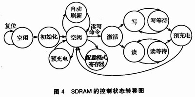
SDRAM (Synchronous Dynamic Random Access Memory) is a kind of volatile memory, which is widely used in its large capacity and low price. However, its control logic is complex, requiring periodic refresh operations, row and column management, different delays, and command sequences. 4 is a control state transition diagram of the SDRAM.
2.4 MCU Control CH376 Module CH376 is a domestic file management control chip used for reading and writing files in U disk or SD card. CH376 has built-in SD card communication interface, FATl6, FAT32 and FAT l2 file system and other firmware, no need to write the underlying protocol, simple control, provide 2 MB, 24MHz SPI device interface, support SPI serial bus connected to the microcontroller. The CH376 application connection diagram is shown in Figure 5.

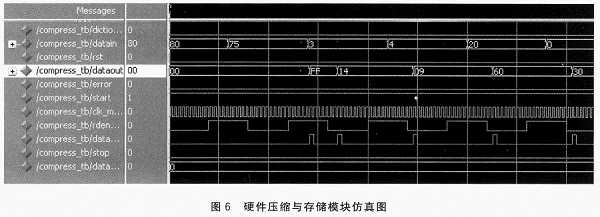
3 After the system simulation and test program is written, it is simulated by Modelsim language simulation software. ModelSim provides a friendly simulation environment and is a single-core emulator that supports VHDL and Verilog hybrid simulation. It uses direct optimization of the compilation technology, Tcl/Tk technology and single-core simulation technology. The compilation and simulation speed is fast, and the compiled code has nothing to do with the platform. It is the preferred simulation software for FPGA/ASIC design. The hardware compression and storage module simulation is shown in Figure 6. Simulation results show that hardware compression is fully consistent with software compression.
Conclusion This paper designed a car CAN bus acquisition system based on "FPGA + MCU". Using the advantages of FPGA, two modules of data compression and SDRAM control are written as the core part of the storage system. The SD card storage controller is designed with the strong control and simple features of the single-chip microcomputer as the final storage medium of data to facilitate users. Read data directly on the computer. Experiments show that the system works stably and is suitable for recording data for a long time.
Daewoo Diesel Generator,Daewoo Diesel Generator Set,Daewoo Diesel Generator Set 550Kw,50Hz Doosan Generator Set
Jiangsu Lingyu Generator CO.,LTD , http://www.lygenset.com