Tags: ISDB-T Technology MBMS
This article refers to the address: http://
1 Introduction
In the United States, Europe, South Korea, Japan, mobile TV services have gradually become an important part of mobile value-added services, and the industry is regarded as the next most potential growth point of telecom value-added services, and even considered to be the "killer" of 3G. "One of the applications. The mobile TV market contains huge business opportunities. Industry experts predict that the total number of annual subscriptions for mobile TV will reach 27 billion US dollars in the next 10 years. By 2010, the total number of users worldwide will reach 250 million. The facts have also proved that the US SPRINT company has developed 300,000 monthly renters for a monthly fee of $10. In China, by the time of the 2008 Beijing Olympic Games, mobile TV may actually enter the lives of the people, and it will become commonplace to watch TV programs on mobile phones.
At present, various bearer technologies related to mobile TV services are developing rapidly. The United States, Europe, South Korea, and Japan all have their own standards. China also has the technology of independent intellectual property rights, which has formed a situation in which multiple bearer technologies coexist.
2. Introduction to mobile TV bearer technology
There are three main types of mobile TV bearer technologies: the way of using mobile networks (3GPP MBMS technology and streaming media technology), the way of using satellite networks (Korean S-DMB and European S-DMB technology), using digital terrestrial broadcasting (European DVB-H technology, Japanese ISDB-T technology, Korean T-DMB technology, Qualcomm MediaFlo technology and domestic mobile TV technology, such as Tsinghua digital terrestrial TV technology DMB-T and Shanghai Jiaotong University digital terrestrial TV technology ADTB-T, etc.).
2.1 Ways to achieve with mobile networks
At present, domestic operators provide mobile TV services based on GPRS and CDMA 1x networks. This mobile TV service actually uses streaming media technology to introduce mobile TV as a data service, using point-to-point rather than broadcast. Way to transfer data. Whether it is a GPRS mobile phone or a CDMA 1x mobile phone, it is necessary to install corresponding playing software on the mobile terminal, and the corresponding television program is organized and provided by the operator or through the corresponding SP.
Streaming media uses client/server mode to store continuous image and sound information on the network server. The server sends data streams according to the request sent by the mobile phone. The mobile phone can be downloaded and played through GPRS or 3G network to support on-demand and live broadcast services. Its network structure is shown in Figure 1.
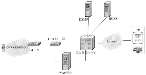
Figure 1 Mobile phone TV service network structure realized by streaming media technology
In the peer-to-peer transmission of streaming media, when a large number of users need to download high-speed data, the source and each receiving user have their own links, which consumes a large amount of mobile network resources and easily causes network congestion. For real-time TV or video live broadcast services, there is no advantage in the cost of hosting. However, the streaming media method can be adapted to a personalized service, such as a video on demand service.
With the application of high-speed broadband data services for mobile users, when a large number of users receive the same high-speed data at the same time, since the content to be transmitted is data that each user needs to receive, if the source establishes a link with each receiving user, each piece The same data is repeatedly sent on the link, which causes duplication and waste of resource usage. Therefore, there is a need for a mobile broadcast multicast technology that can effectively utilize source and wireless network air interface resources to reduce the amount of data transmitted in the network and overcome network congestion. The 3GPP R6 standard was launched in 2002 and specifies the MBMS standard for mobile broadcast multicast services that implement mobile TV functions using UMTS networks. As long as minimal changes are made in the existing UMTS network, most of the functional entities and air interface protocols do not need to be changed to implement MBMS.
The MBMS network (see Figure 2) is based on the original UMTS network structure, adding a network element BM-SC, which is the entry of the content provider, for authorizing and initiating the MBMS bearer service in the mobile network, and transmitting the MBMS according to the scheduled schedule. content. Its functions include: authorizing third-party content providers to authenticate and charge users; providing MBMS transmission related parameters to GGSN; initiating and terminating MBMS transmission resources; receiving content from external data sources, using error recovery mechanism for retransmission; scheduling MBMS session transmission, regaining external data content, marking each MBMS session with "MBMS session identifier", enabling users to distinguish between MBMS retransmission sessions; service announcements, including media descriptions, session descriptions, and so on.
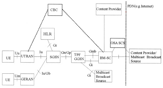
Figure 2 MBMS network structure
For the existing UMTS/GSM packet network function entities GGSN, SGSN, RNC/BSC and UE, it is also necessary to add MBMS related functions and processes, such as resource management in a predetermined multicast or broadcast service area, to support service initiation and suspension; The mobility management of the MBMS receiver, and the concurrency consideration of the ordinary voice data function.
A new physical channel MICH (MBMS Indicator Channel) has been added to the MBMS technology to transmit an MBMS notification indication, and to subscribe to an MBMS user subscribed to a certain service. New logical channels MTCH, MCCH, MSCH channels are added, which are mapped to the FACH transport channel for carrying service data and related control information. When there are many custom service users, the FACH channel transmission is used in a broadcast manner. When the user of the customized service rarely uses a dedicated channel, since the transmission power of the FACH channel is larger than the DCH, the user of the customized service rarely wastes power. At this time, it is possible to switch from the broadcast transmission mode to the dedicated transmission mode to save power resources.
When the end user moves to the cell boundary under different base stations, the macro diversity technique is used to simultaneously receive television data from the two base stations (see Figure 3). When the macro diversity technology is implemented, the network side is required to perform content synchronization and a certain degree of time synchronization between the two cells for the same MBMS service.
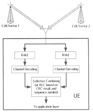
Figure 3 MBMS macro diversity technology
MBMS can apply two modes of business: multicast mode and broadcast mode. The broadcast mode is close to the digital TV service, while the multicast mode focuses on and locates the group service. The multicast mode provides better charging features, including service subscription, access, and push. Users need to subscribe to the corresponding multicast group, perform service activation, and generate corresponding accounting information. The broadcast service does not need all the cells in the cell. Users can make this business available. Because the multicast and broadcast modes differ in business requirements, their business processes are different (see Figure 4a, Figure 4b).
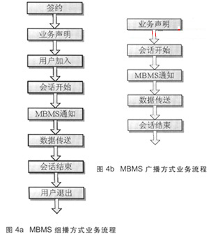
The contract is to establish a multicast service to the operator, the operator grants the user the right to use the service, and the user registers the bill; the MBMS service announcement mechanism enables the user to obtain the relevant information of the MBMS service; the broadcast multicast service center BM-SC initiates The session starts, triggering the establishment of the corresponding network resource by the MBMS data transmission; the network side uses the MBMS notification to enable the UE to confirm the MBMS data being transmitted or about to be transmitted. Finally, the session initiated by the broadcast multicast service center BM-SC ends, triggering the release of the corresponding network resources by the MBMS data transmission.
The service in multicast mode is in progress. When a new user wants to join a multicast group, the network is told to receive multicast information. The UE sends a join request to the GGSN through the bearer channel between the established UE and the GGSN. . Users can join a multicast group at any time, but they need to be authenticated as a charging basis. When a user no longer wants to receive multicast information, he can quit the multicast group at any time.
2.2 Ways to achieve using satellite networks
The use of cellular network resources to transmit broadcast television video is indeed a reliable way to carry. However, when the amount of data is large, it also brings the delay of the transmission network and the risk of congestion, which affects the communication reliability of other services in the network. If a method is used to separate the huge amount of transmission of television programs and manage the interaction of billing data, it can ensure the transmission of high-quality television programs and the collection of user information and tariff statistics, while at the same time not occupying the resources of the cellular network. It should be possible to remove certain obstacles to the scale of the mobile TV business to some extent.
At present, South Korea and Europe are pushing a mobile TV broadcasting method (S-DMB) that uses a mobile phone to receive satellite broadcasted television program signals. S-DMB mainly studies the combination of satellite and terrestrial repeaters on existing 3G mobile networks to provide mobile broadcast and multicast services, and improve the multimedia service provision capability of 3G networks. It complements the respective advantages of the broadcast television network and the mobile communication network. The downlink broadcast channel is provided by the satellite, and the broadcast data is broadcasted through the high-bandwidth digital broadcast television network. The uplink uses the mobile network to transmit interactive services, and the mobile network provides interactive channels, completes service navigation, ordering and activation, and authentication and billing functions. S-DMB-capable mobile terminals can simultaneously receive S-DMB signals when connected to a GSM or UMTS network.
(1) S-DMB technology
The S-DMB can be regarded as an MBMS technology that provides broadcast capability on the dedicated frequency band MSS (2170 to 2200 MHz). Since the MSS band is close to the IMT2000 downlink core band (2110 to 2170 MHz), this is extremely advantageous for the cost of the terminal and the deployment of the ground repeater. Therefore, S-DMB can be seen as an extension of MBMS (also known as S-MBMS), which belongs to a specification system as well as MBMS. S-DMB's technology to maximize UMTS reuse includes spread spectrum communication, modulation, etc., while increasing the IMR (Intermediate Module Repeater) to meet indoor coverage requirements, and can rely on the powerful macro diversity capabilities of UMTS terminals to support coverage from satellites. Switching to the ground repeater coverage and switching between two different ground repeater coverages.
(2) S-DMB networking structure
The networking structure of S-DMB is shown in Figure 5. Based on the existing network architecture and functional interfaces of 3GPP MBMS, satellite-related functional modules are added. At the same time, there are also a small number of functions added to BM-SC and UE. A network of mixed satellites and ground repeaters.
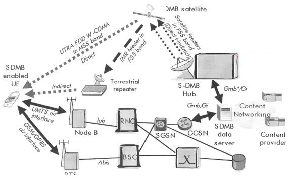
Figure 5 S-DMB network structure
In Figure 5, the high-power satellite will relay and amplify the uplink Ku-band modulated S-DMB signal received from the S-DMB Hub, and down-convert the signal to the IMT2000 satellite band signal and send it to Mobile phone users. In addition, the satellite downconverts these signals to the Ku-band carrier frequency to provide signals to the ground repeater. For the S-DMB signal, the satellite is transparent and plays only the role of a band conversion repeater.
(3) Types of ground repeaters
â— Repeater for frequency conversion (Frequency Conversion) function
The repeater of the frequency conversion function relays and amplifies the Ku-band modulated S-DMB signal received from the satellite, and down-converts it into the downlink IMT2000 satellite frequency carrier frequency and transmits it to the end user. This type of repeater and satellite operate in the same IMT2000 band, enabling the user to receive an S-DMB signal modulated to multiple echo signals reflected by the same IMT2000 carrier frequency. This type of repeater will be the most deployed repeater product, which can be co-located with existing 2G and 3G base stations for the purpose of satellite coverage in urban areas.
â—On Channel function repeater
The On Channel function repeater is used to relay and amplify the S-DMB signal modulated by the downlink IMT2000 satellite band, receive the signal from the satellite, and send it to the end user. This type of repeater is used to extend the coverage of a particular indoor environment.
The S-DMB Hub is used to generate and transmit S-DMB signals, and to modulate the S-DMB signals onto the uplink Ku-band carrier frequency to provide signals to the satellites. The Hub includes a Ku-band ground station that is signaled by the NodeB's modem, which is controlled by the RNC. The Hub also includes a simplified 3G core network device that interfaces with one or several 3GPP specifications defined BM-SCs via the GmbH interface.
2.3 Ways to achieve using digital terrestrial broadcasting
The mobile TV technology method is realized by integrating digital TV and mobile phone, so it also promotes the convergence of the two networks of digital TV broadcasting network and mobile cellular communication network. At present, a method of installing a digital television receiving module on a mobile phone terminal and directly obtaining a digital television signal by receiving a terrestrial broadcast repeater has become one of the implementation methods of mobile TV. This kind of mobile digital TV standard is realized by digital terrestrial broadcasting. This paper mainly introduces DVB-H in Europe and ISDB-T technology in Japan.
(1) DVB-H technology
The DVB series of standards was first proposed by the DVB project team in the early 1990s. The terrestrial broadcast version of DVB-T (Digital Video Broadcasting-Terrestrial) was developed in the mid-1990s and acquired ETSI (European Telecommunications Standards) in February 1997. The Institute's recognition has become the standard for terrestrial digital television broadcasting in Europe. At present, many countries and regions around the world have used or adopted the DVB-T standard. Although there is no DVB-H network in China, the DVB-T system has already been implemented in China. Beijing and Shanghai have adopted the system to bring TV news and sports. TV shows, stock reports and commercials are delivered to thousands of city cars.
DVB-H (Digital Video Broadcasting-Handheld) is a technology developed based on DVB-T, which provides multimedia services to handheld terminals through terrestrial digital broadcasting networks. It can transmit multiple video channels and audio to mobile terminal users. Channel. This technology is mainly to solve the problems of power consumption, performance problems in the mobile environment, and flexibility of network design when providing digital TV broadcasting services to mobile handheld terminals.
The DVB-H system relies on the DVB-T transmission system to enable the handheld terminal to stably receive broadcast television signals by adding certain additional functions and improved techniques. DVB-H can ensure that mobile terminals receive digital TV programs in mobile environments and micro-power conditions, which is well suited to 3G network applications. In addition to its own functions, the 3G network also acts as a reverse control channel for the DVB-H network, transmitting service signaling such as video on demand, TV voting, TV browsing, interactive games, and providing a variety of personalized multimedia services. Thereby achieving the fusion of the two networks.
When the DVB-H operating system is networked (see Figure 6), the networking equipment includes the modulator, transmitter, IPE, IPDC core application system, and the IP network equipment (such as Ethernet switches, routers, and firewalls) necessary to connect these devices. ) and data transmission equipment. Data transmission can be implemented based on SDH, PDH or microwave.
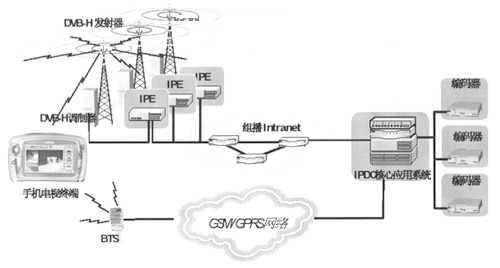
Figure 6 DVB-H network structure
The IPDC application system is connected with GSM/GPRS/UMTS to implement billing for users, authenticate and complete user preview and ordering of services, so mobile operator's authentication, billing, customer service, customer management, etc. are also required. Cooperate. When the IPE (IP Encapsulator) receives the IP data stream transmitted from the encoder, it sets each channel (or program) according to the IP multicast address (source address and destination address) corresponding to each channel (or program). Its corresponding channel (or program) number. Mobile phones supporting DVB-H require additional DVB-H antennas and RF processing modules.
The DVB-H operating band uses the UHF band of 470 to 862 MHz, and the frequency bandwidth can be 5 MHz, 6 MHz, 7 MHz or 8 MHz.
The COFDM modulation scheme is used to perform modulation using a plurality of orthogonal subcarriers equally spaced in frequency. According to the number of subcarriers, it can be divided into 3k, 4k and 8k. For each subcarrier, its modulation mode can be divided into QPSK, 16QAM, and 64QAM. The transmission rate is related to the number of carriers, the subcarrier modulation mode, the guard interval, and the coding rate. The transmission rate ranges from 4.98 to 31.67 Mbit/s.
The coverage radius of a cell of a DVB-H single frequency network is approximately 40 to 60 km. Multiple simultaneous wireless transmitters are included in a single frequency network that transmit exactly the same bit stream at exactly the same frequency. In addition, additional indoor coverage and seamless switching between cells must be considered when networking. In a single frequency network, the number of users that can be supported is not limited. However, compared to outdoor reception, the coverage of indoor reception is reduced due to the penetration loss (approximately 11 dB). Therefore, in areas where the signal strength is weak, special indoor coverage is required to ensure normal reception indoors.
DVB-H introduces time slicing and MPE-FEC technology.
â— Time slicing uses burst mode to transmit data, and each burst time slice transmits a service. The service will occupy the entire data bandwidth separately in the time slice and indicate the moment when the next same business time slice is generated. The advantage of time slicing is that the receiver can do energy-saving processing to achieve low power consumption during business idle time. Another advantage is that the neighbor cells are monitored in the off-time of the service, and the switching between the single-frequency networks can be completed through a single receiver (antenna) to ensure the continuity of the service.
MPE-FEC (MultiProtocol Encapsulation-Forwarding Error Correction) is an error correction technique in which RS (Reed-Solomon) error correction coding is added to IP packets in order to improve reception performance. DVB-H uses MPE-FEC to improve C/N, Doppler performance, anti-pulse interference capability and error correction capability in mobile channels. Experiments have shown that even in very bad reception environments, proper use of MPE-FEC can recover IP data without errors. This additional error protection layer (MPE-FEC) improves reception in weak signal conditions, increases interference immunity, and supports mobile high-speed data transmission.
Due to the transmission of IP data packets, the mobile terminal receiver generally only turns on 10% of the entire transmission time, and the rest of the time is completely turned off, which greatly reduces the power consumption of the mobile terminal. It can provide a transmission speed of up to 15 Mbit/s in an 8M bandwidth. If a channel occupies 200 to 300 kbit/s, the capacity is large enough to transmit more than 40 to 50 broadcast quality TV channels.
(2) ISDB-T technology
ISDB-T is an independent digital TV standard development project initiated by Japan in 1996, introducing segmented OFDM technology. In 1998, Japan formulated this technology body called BTS-OFDM as the Japanese terrestrial digital television broadcasting transmission standard ISDB-T. In 2001, the standard was officially accepted by the ITU as the world's third international standard for digital television transmission.
ISDB-T uses a segmented band with 13 OFDM subbands to divide the entire 6MHz band into 13 subbands, each subband with 432kHz for Bandwidth Segemented Transmission (BST), and different coding types for different BSTs. And modulation mapping (QPSK or QAM, etc.) to meet the needs of different services, such as the lower technical requirements for channel coding for transmitting multimedia text files, and higher requirements for mobile video reception. Since ISDB-T adopts the technology of carrier division, the terminal can perform narrowband reception, thereby effectively reducing the power consumption of the terminal.
ISDB-T uses different carrier modulation schemes and inner code coding rate for different BST segments, which in turn provides layered transmission characteristics. By layered propagation, multiple types of broadcasts with different propagation characteristics (modulation method, coding rate, etc.) can be simultaneously transmitted in 1 ch (eg, 6 MHz).
As shown in FIG. 7, a plurality of segments can be flexibly combined according to different transmission services. For example, 9 segments can be combined to transmit HDTV, and 3 segments can be combined to transmit the vehicle TV, and the OFDM segment group with different parameters can be transmitted to achieve hierarchical transmission. Three business layers (three different segment groups) are available in one terrestrial channel. Part of the program in the transmission channel can be received by using a narrowband receiver with only one OFDM segment.
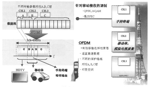
Figure 7 ISDB-T layered propagation mode
3, the conclusion
Comparing the various mobile phone bearer technologies introduced above, the service capacity supported by terrestrial digital TV bearer technology in the same frequency bandwidth is more advantageous than other methods. The ground method is more suitable for urban or regional business development, while the satellite method is suitable for wide-area or national business development, but its network construction requires satellite support, and the initial cost is high. While MBMS utilizes mobile network bearers, it occupies valuable mobile network resources, but because MBMS is based on cell coverage, it can provide services based on smaller areas and user location-related services, and is completely operated and controlled by mobile operators, making mobile operations Businesses have greater flexibility and control. For real-time TV or video live broadcast services, terrestrial digital TV bearer, satellite bearer, and MBMS technology are significantly better than point-to-point streaming media in terms of capacity and bearer cost.
Many mobile TV bearer technologies have their own characteristics, advantages and disadvantages. The discussion and debate on technical standards are also deepening. Which standard will be adopted in China's future commercial use is still inconclusive. However, with the continuous improvement of the mobile TV bearer technology, the prospects of the mobile TV business are also optimistic.
Inner Battery,Electric Bike Battery,Ebike Battery 36V 12Ah,Electric Bicycle Lithium Battery
Changxing Deli Technology Co., Ltd. , https://www.delipowers.com