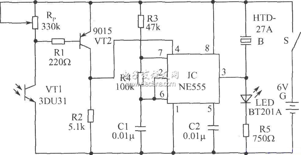
Circuit principle: An audio oscillator is composed of IC, R3 and R4, C1, and its oscillation frequency is estimated by the formula f=1.443/(R3 2R4)C1. The circuit audio is set at around 580Hz. Normally, when the phototransistor VT1 is not subjected to light, its internal resistance is very large, so that VT2 is turned off, and the reset terminal 4 of the IC is at a low level and is in a main reset state, and the 3 pin is at a low level, so that the circuit is not Sound and light signals. When any remote control button of the infrared remote control transmitter is pressed, its infrared pulse signal is received by VT1, so that the internal resistance of VT1 is small, the corresponding VT2 is turned on, and the 4 pin of the IC is high, and the IC is in audio. In the oscillation working phase, the 3-pin outputs an audio signal, so that the piezoelectric ceramic sheet B emits a sound and the LED is illuminated. Remote detector circuit:
Wifi Dongle,LTE Wingle,LTE Dongle,Sim Dongle
Shenhzhen Tongheng Weichuang Technology Co., Ltd , https://www.thwclte.com