With the rapid development of electronic technology, the control system based on single-chip microcomputer has been widely used in industries such as industry, agriculture, electric power, electronics, intelligent buildings, etc. As the main body and core of embedded control system, microcomputer replaces the routine of traditional control system. Electronic circuit. The development and maturity of building intelligence has also laid a solid foundation for the popularization and application of single-chip based lighting control systems. The indoor lighting control system based on single chip AT89C51 and its principle are introduced, and an effective energy saving control method is proposed. The system uses the more mature sensing technology and computer control technology, and uses multiple parameters to control the indoor lighting of the school classroom. The system is composed of a single-chip microcomputer and a variety of interface circuits. There are six main parts: AT89C51 chip, optical signal acquisition circuit, human body signal acquisition circuit, clock control circuit DS12887, output control circuit and timing monitor circuit.
Main controller circuit design
The main controller adopts AT89C51 single-chip microcomputer as the microprocessor. AT89C51 is a low-voltage, high-performance CMOS 8-bit single-chip microcomputer produced by American ATMEL Company. The chip contains 4K bytes of re-writable Flash read-only program memory and 128 bytes of random memory. Take data memory (RAM), the device is produced by ATMEL's high-density, non-volatile memory technology, compatible with the standard MCS-51 instruction system, built-in general-purpose 8-bit central processing unit (CPU) and flash memory unit. The peripheral interface circuit of the main controller system is composed of a keyboard, a digital display and a driving circuit, a crystal oscillator, a watchdog circuit, and a communication interface circuit. The hardware circuit schematic of the main controller system is shown in Figure 2-2.
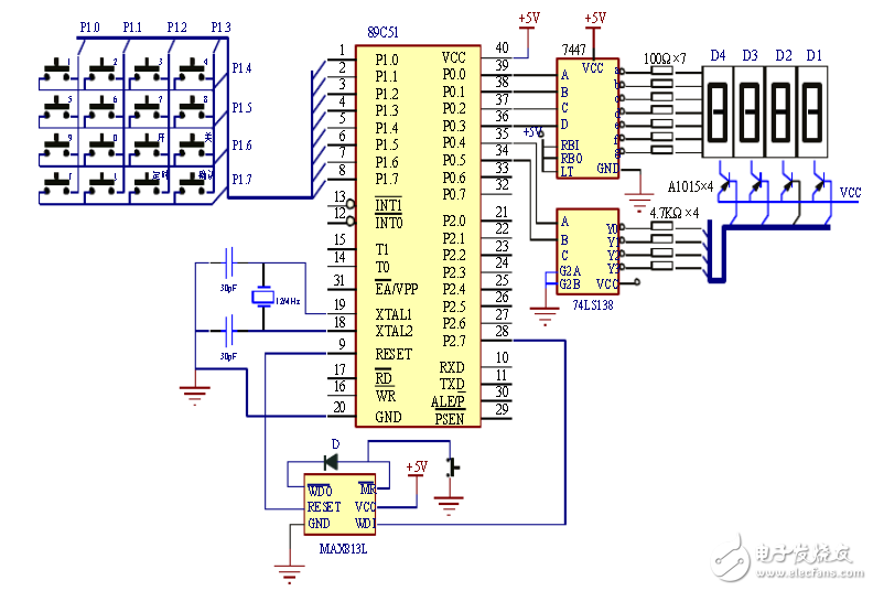
Figure 2-2 Schematic diagram of the hardware circuit of the main controller system
Design of RS485 communication circuit
In various distributed distributed control systems, one single-chip microcomputer is often used as the host, and multiple single-chip microcomputers are used as slaves. The host controls the operation of the whole system; the slaves collect signals to realize on-site control; and the master and slave are connected by bus. , as shown in Figure 2-4. The host sends information to each slave (point to point) or multiple slaves (broadcast) through TXD, and each slave can also send information to the host, but the slaves cannot communicate freely, and they must transmit information through the host. .
The wired communication mode of the system uses RS485 bus for communication, and the RS485 standard supports half-duplex communication. It only needs three lines to transmit and receive data, and has the ability to suppress common mode interference. The receiving sensitivity can reach ±200mV. The communication distance is increased, and the communication distance can reach 1200m at 100K bps. If the communication distance is shortened, the maximum rate can reach 10M bps. The master-slave communication method is used here, the host is operated by the master controller, and the slave is the sub-controller. The master is in a dominant and dominant position. The slave receives and transmits data in an interrupted manner. The information sent by the master can be transmitted to all slaves or designated slaves. The information sent by the slave can only be received by the master. Direct communication. The communication circuit diagrams of the master and slave are shown in Figure 2-5 and Figure 2-6, respectively.
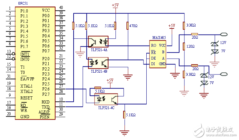
Figure 2-5 Host communication circuit diagram
  
Ture Wireless Earbuds,True Wireless Earphones,Bluetooth Wireless Earbuds,Ture Wireless Earplugs
TOPWAY EM ENTERPRISE LIMITED , https://www.topwayemltd.com