Transformers are generally considered to be the best choice for converting the complementary output of a high-speed current-output DAC to a single-ended voltage output because the transformer does not add noise or consume power. Although the transformer performs well under high-frequency signals, they cannot. Handling the low frequency signals required by many instrumentation and medical applications. These applications require a low power, low distortion, low noise, high speed amplifier to convert the complementary current into a single-ended voltage. The three circuits shown here accept the DAC. Complementary output current and provide single-ended output voltage. Compare the distortion of the latter two with the transformer solution.
Differential Amplifiers: The AD8129 and AD8130 differential-to-single-ended amplifiers (Figure 15) are used in the first circuit (Figure 16). They have very high common-mode rejection at high frequencies. The AD8129 is stable with a gain of 10 or more. The AD8130 is stable at unity gain. Their user adjustable gain can be set by the ratio of the two resistors, RF and RG. The AD8129 and AD8130 have high input impedance on pins 1 and 8. Not affected by the gain setting. The reference voltage (VREF, pin 4) can be used to set the bias voltage, which is multiplied by the same gain as the differential input voltage.
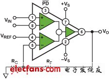
Figure 15. AD8129/AD8130 Difference Amplifier
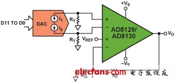
Figure 16. DAC Buffer with AD8129/AD8130
Equations 1 and 2 show the relationship between the output voltage of the amplifier and the complementary output current of the DAC. The termination resistor RT performs the current-to-voltage conversion; the ratio of RF to RG determines the gain. VREF is set in Equation 2. Is 0.
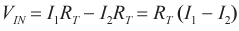 | (1) |
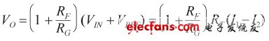
| (2) |
In Figure 16, the circuit uses a four-channel high-speed, low-power, 14-bit DAC in which the complementary current output stage increases speed and reduces the distortion of the low-power DAC.
Figure 17 shows the spurious-free dynamic range (SFDR) of a circuit as a function of frequency using a DAC and AD8129, where RF = 2kΩ, RG = 221Ω, RT = 100Ω, and VO = 8Vp-p, two The power supply voltage corresponds to different values. The AD8129 is selected here because it provides a larger output signal, which is stable at G = 10, and has a higher gain-bandwidth product than the AD8130. In both cases, SFDR is generally It is better than 55dB, more than 10MHz, and there is about >3dB improvement at low power supply voltage.
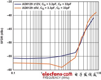
Figure 17. Distortion of DAC and AD8129 VO = 8 V pp
Indoor Fixed Advertising LED Billboard
This series is professionally used for indoor fixed installation of LED display, a variety of installation solutions such as wall installation, simple shelf installation, photo frame installation and so on. Displays advertising video content well indoors. It is suitable for bars, KTV, indoor meeting rooms, exclusive stores, inside shopping malls, indoor stores and so on. Indoor Fixed Advertising LED Billboard,beautiful cabinet design, seamless connection to realize large-screen display advertisement, high-definition smooth video playback function.

Indoor Fixed Advertising Led Billboard,Indoor Led Wall Billboards,Indoor Fixed Led Billboards,Shopping Mall Led Display
Guangzhou Cheng Wen Photoelectric Technology Co., Ltd. , https://www.ledscreencw.com