Based on AT89S51 single-chip microcomputer, this paper proposes a design scheme based on DC motor speed regulation and speed measurement system, and then gives the main circuit structure of the system, as well as the design of drive circuit and system software. This program makes full use of the advantages of the single-chip microcomputer, and has the characteristics of high frequency and fast response.
0 Preface
DC motors are commonly used in industrial production, with good starting and braking performance. Early DC motor control was based on analog circuits, using operational amplifiers, nonlinear integrated circuits, and a small number of digital circuits. The hardware part of the control system is complex, single-function, and difficult to debug. This solution uses a single-chip control system, so that many control functions and algorithms can be completed by software technology, which provides greater flexibility for the control of the DC motor and enables the system to achieve higher performance.
1. Principle of PWM DC speed regulation based on single chip microcomputer
PWM (Pulse Width Modulation) is referred to as pulse width modulation. It is a technology that uses the digital output of a microprocessor to control an analog circuit. It is widely used in many fields such as measurement, power control and conversion. Pulse width modulation is an analog control method that modulates the bias of the base of the transistor according to the change of the corresponding load and changes the on-time of the transistor. It is a very effective technique to control the analog circuit by using the digital output of the microprocessor.
PWM can be applied in many aspects, such as motor speed control, temperature control, pressure control, etc. In the PWM drive control adjustment system, the power is turned on and off at a fixed frequency, and the length of the "on" and "off" times in one cycle is changed as needed. By changing the "duty cycle" of the voltage on the armature of the DC motor
To change the average voltage, thus controlling the speed of the motor. Therefore, PWM is also called "switch drive". The duty cycle of PWM determines the average voltage output to the DC motor. Therefore, by adjusting the duty ratio, it is possible to adjust the output voltage steplessly continuously.
2. The main circuit design of speed regulation and speed measurement system
The whole system consists of input circuit, PWM modulation, speed measurement circuit, drive circuit, control part and display. The PWM modulation uses AT89S51 single-chip microcomputer to realize the frequency and duty cycle adjustment through software.
2.1 DC motor speed control design
The driving circuit is separated by an optocoupler protection circuit. The control part is composed of a single chip microcomputer and a peripheral circuit to realize various control requirements. The peripheral circuit mainly completes the acquisition, operation and speed control of the input signal, and the display part adopts a four-digit common digital tube. . The system block diagram is shown in Figure 1.
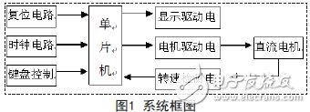
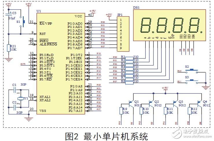
The hardware aspect is based on STC89C51 single-chip microcomputer, and the minimum system is composed with reset circuit, crystal oscillator circuit, drive circuit, speed measuring circuit, keyboard and LED display module. The software generates the output of the PWM pulse signal, the data transmission of the keyboard and the LED display by programming in the C51 language. The speed gear setting value is adjusted by the keyboard to realize tracking according to the set value, and is displayed on the LED display. Finally, the PWM pulse signal is output by the single chip microcomputer, and the speed is fed back to the CPU through the speed measuring circuit and the speed is displayed on the LED display through the CPU. In order to reach the desired speed.
2.2 display circuit design
The LED adopts the dynamic display mode, which displays the actual speed of the motor through the four-digit digital tube to facilitate the monitoring of the system. The system uses a four-digit digital digital tube, uses a 9012 triode switch circuit to drive, and controls the display of the digital tube.
2.3 reset circuit
The reset circuit of the MCU is like the restart part of the computer. When the MCU system is running, the program inside the reset button is automatically executed from the beginning. The reset circuit adopts two modes of power-on automatic reset and manual reset, and C3, R21 and S1 form a reset circuit.
2.4 clock circuit
The clock circuit design of the system is an internal mode, that is, the use of an internal oscillation circuit. The AT89 family of microcontrollers has a high-gain inverting amplifier that is used to form the oscillator. Pins XTAL1 and XTAL2 are the input and output of this amplifier, respectively. This amplifier forms a self-excited oscillator together with an off-chip crystal resonator as a feedback element. The external crystal resonator and the capacitors C1 and C2 form a parallel resonant circuit connected to the feedback loop of the amplifier.
High Torque Stepper Motors provide the highest torque in a wide range of frame sizes. For many applications, these motors offer a high-performance, cost-effective alternative to pneumatic, hydraulic and servo motor systems.
High torque stepper motors are perfect for the following applications: Infusion systems, Diagnostic analyzers, Pipettes
Power hand tools, Valve actuation, Access systems, Material handling, etc.
High torque stepper motor,High precision stepper motor,High accuracy stepper motor,High torque stepper motor price,High holding torque stepper motor,High torque geared stepper motor
Shenzhen Maintex Intelligent Control Co., Ltd. , https://www.maintexmotor.com