The current TPMS (TIre pressure monitoring system) is mainly divided into two types, one is indirect and the other is direct. The direct TPMS system has been affected by its poor alarm accuracy and interference by the shielded electromagnetic waves and magnetic fields of the hub in wireless transmission, which has affected its further development.
Based on the radio frequency chip produced by Nordic, this paper introduces the circuit design and solution of the wireless transceiver system of the automotive TPMS system, thereby improving the above-mentioned direct TPMS system.
1 Design of TPMS system 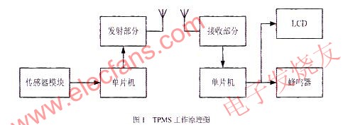
The TPMS system mentioned in this article is completed by sending and receiving radio frequency information and prompting related information. In the tire part, there are mainly a pressure detection module and a radio frequency transmission module, and in the driver part, there are mainly a radio frequency reception module and a display alarm module.
The pressure detection module mainly detects the pressure data of the measured tire in real time, and stores the data to the central processor for corresponding changes, and waits for the radio frequency transmission module to transmit. After the RF receiving module receives the data, it processes the data accordingly and displays the data on the accessory LCD, and judges the safety of the data. When the tire pressure is found to exceed the acceptable range, the buzzer will alarm Remind the driver. The specific working principle diagram is shown in Figure 1.
2 Comparison and selection of wireless transceiver chips
Because there are many types and numbers of wireless transceiver chips, the choice of wireless transceiver chips is crucial in the design. The correct choice can reduce the development difficulty, shorten the development cycle, reduce costs, and bring products to market faster. When choosing a wireless transceiver chip, you should consider several factors: power consumption, transmit power, receiving sensitivity, the number of peripheral components required by the transceiver chip, chip cost, and whether Manchester encoding is required for data transmission.
Several important indicators used to evaluate wireless data transmission and reception are: receiving sensitivity, dynamic range, selectivity, receiving frequency stability, transmitting power ratio, efficiency, transmitting frequency range, power consumption and other factors. The following compares the performance of three popular wireless transceiver chips on the market at the current stage, as listed in Table 1. 
Comparing the expressions in Table 1 and the technical indicators, for receiving and sending data, the greater the frequency band range, the higher the sensitivity, the smaller the receiving current under the same bar, the larger the transmitting current, the fewer peripheral devices are required. The more widely used transceiver chip applications, and can be suitable for a variety of situations.
Based on the above considerations, the superiority of nRF905 is obvious, so it is most suitable to choose nRF905 in this design.
3 Introduction to nRF905
The wireless transceiver chip nRF905 is a single-chip wireless transceiver integrated chip launched by Nordic in Norway. nRF905 is a monolithic RF transceiver working in the 433/868/915 frequency band. Because it uses the international ISM frequency band, there is no so-called frequency band limitation. nRF905 is composed of fully integrated power management, frequency synthesizer, modulation receiver, power amplifier, crystal oscillator and regulator. nRF905 has the characteristics of ShockBurst, which can automatically process the preamble and CRC check code in the data packet. Through the SPI interface, the configuration operation of nRF905 can be easily programmed. The power consumption of nRF905 is very low. In the transmission mode, the power consumption for transmission with an output power of -10dBm is only 11mA; the same power consumption in the reception mode is 12.5mA. And its POWERDOWN power-down mode can save more power.
3.1 Control mode of nRF905
nRF905 has two activation modes and two power saving modes.
Activation modes include ShockBurst RX reception mode and ShockBurst TX transmission mode. Power-saving modes include PowerDown and SPI-programming power-down and SPI programming mode and Standby and SPI-programming standby and SPI programming mode.
The settings of TRX_CE, TX_EN and PWR determine the control of the mode. The specific controls are listed in Table 2.
3.2 The connection of the one-chip computer and nRF905
The nRF905 communicates with the outside world through an SPI interface, the rate is determined by the interface speed set by the microcontroller. In RX mode, the address match (AM) and data ready (DR) signals inform the MCU that a valid address and data packet have been received, and the microcontroller can read the received data through SPI. In TX mode, the wireless communication module automatically generates the preamble and CRC check code, and the data ready signal notifies the MCU that the data transmission has been completed.
The AT89S52 series of single-chip microcomputers that are fully compatible with 8051 produced by ATMEL are used here. Because communication with the module is required, the control of the module is carried out through the SPI interface bus of nRF905. Because AT89S52 does not have a special SPI bus, Here, in order to communicate with the wireless module of nRF905, the I / O port of the single-chip microcomputer is used for software programming to simulate the SPI timing to realize the SPI interface. Here, the pins used for mode control (TXEN, TRX_CE, PWR) and the SPI interface control (MISO, MOSI, SCK, CSN) are connected to the P2 port of the microcontroller, and the status output (AM, DR, CD ) The pin is connected to 2 to 4 bits of the P3 port of the single-chip microcomputer. Figure 2 shows the simple circuit connection between the single-chip microcomputer and the nRF905 module.

4 System software design
4.1 SPI interface inspection
Because the control of nRF905 is carried out through the built-in SPI bus, it is necessary to ensure that the operating system such as single-chip microcomputer and other operating systems can communicate with the nRF905 through the analog SPI bus of the I / O port before the overall program design. Therefore, this system has designed a program part for checking SPI interface. Because there is a configuration register inside the nRF905 module, you can write and read data through SPI, compare the results before and after the same and judge the correctness of the SPI operation.
If the array data obtained by the program operation is exactly the same as the written data, then it can be explained that the SPI interface of the nRF905 module for this operation is all normal.
4.2 Programming of wireless radio frequency communication
The key part of this system is the wireless radio communication part. When the tire pressure is collected, whether the data can be quickly transmitted is the premise and guarantee of whether the TPMS system can work normally.
Wireless radio frequency communication is divided into the transmitting part of the tire part and the receiving part of the cab.
When the nRF905 module performs a sending operation, its main control unit (in this system is a single chip microcomputer) transmits the address and valid data of the receiving node to the nRF905 module through the SPI interface.
The nRF905 module in transmit mode will be completed internally:
(1) The wireless system is automatically powered on;
(2) The data packet is completed (plus preamble and CRC check code):
(3) Data packet transmission (100kbit / s, GFSK, Manchester encoding).
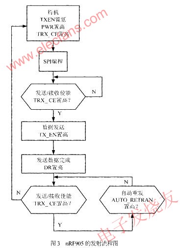
In order to maintain the reliability of the system communication, this system uses the working principle of wireless data retransmission for the transmitting part of nRF905, so here TRX_CE is set to always high level. The specific launch flow chart is shown in Figure 3.
The main task of the receiving part of this system is to continuously detect the radio frequency electromagnetic waves with the same radio frequency in the air. After receiving the electromagnetic waves, the corresponding CD, AM, DR bits are set to 1 in order, and then the reading and writing process begins .
After starting to detect the radio frequency electromagnetic waves, it goes through three processes:
(1) The carrier detection CD is set high;
(2) The address matching AM is set high;
(3) Data ready DR is set high.
Setting DR high means that the data has been received and saved in the internal register of the nRF905 module. The following work is to read data at a certain rate for the nRF905 module in the SPI interface operation mode and then all After reading and writing, the AM and DR bits are reset to zero to ensure the normal operation of the next data reception. The specific reception flowchart is shown in FIG. 4.

5 Experiment and simulation
The communication between nRF905 and the single chip here is carried out by bit communication through the SPI interface. Therefore, when receiving, the corresponding waveform test of the corresponding pin of the SPI should present a square wave. The transmission data of the pressure sensor to observe the waveform is shown in Figure 5.
It can be seen from the figure that the system is completely correct in the process of communication, and the intensity of the electromagnetic wave is very strong, which can completely achieve the purpose of communication.
In the design of this system, the radio frequency wireless communication method is used to establish the TPMS system, which realizes the real-time detection of the pressure and temperature of the car tires. This system uses the currently popular radio frequency communication technology, and performs reliable data transmission in this environment, adapting to the future development trend of short-distance communication. The overall reliability of the system is high, the stability is good, and the cost is low, which is conducive to transplantation and is convenient for adding other functions. If it can be truly applied, the market prospect will be very good.
Portable charger which is also named Power Bank or portable phone charger is popular for charging smart phones and mobile tablet devices. Our portable phone battery charger is compatible with most of the mobile phones in the market . there is no need to worry compatibility if you want to use by yourself or send as a gift .
Provide best power bank.
Perfect compatibility
Our power bank is compatible with most of the mobile phones in the market .
There is no need to worry compatibility if you want to use by yourself or send the Powerbank Phone Charger as a gift.
Share together , more friend ship
Ultra slim and easy to carry
Genuine Portable Battery Mobile Power Bank Charger
Li-Polymer with LED Indicator
Li-polymer battery
Customized the shape
Ultra thin power bank adopts Li-polymer cell inside
High safety performance
Li-polymer cell will not explode
The portable battery charger is designed more friendship , and is Built-in intelligent protect chip to prevent overcharge . we aim to provide the best portable charger for customers .
The advantages of this produce as following :
Ultra thin and easy to carry
High capacity
Dual input & dual output
Dual output more convenient
Both apple and android user can charge and recharge with either micro cable or Lightning Cable .
Power Bank
Power Bank, Power Bank Charger, Powerbank Phone Charger, Power Bank Battery, Portable Battery, Phone External Battery
Hebei Baisiwei Import&Export Trade Co., LTD. , https://www.baisiweicable.com