With the advent of the energy crisis, efficient lighting technology has received widespread attention. Light-emitting diode LED (Light EmitTIng Ddiode) is a device that uses semiconductor PN junction or similar structure to convert electrical energy into light energy. With its advantages of high efficiency, low power consumption, low voltage drive, and long service life, it has been used in many applications. It has been widely used, such as backlight sources of various consumer electronics products-mobile phones, PDAs, and LCD TVs. High-brightness LEDs are an ideal alternative to traditional incandescent lamps, because the former has a much longer life and efficiency than the latter, and unlike compact fluorescent bulbs, these LEDs can work at low temperatures. In order to improve the performance and scope of application of LED lighting circuits, this article will introduce a cost-effective high-brightness white LED (HBLED) dimming method.
For HBLD, the turn-on voltage is as high as 3 to 5 V under high-illuminance working conditions, and the working current can reach 0.15 to 3 A. The luminous brightness of LED is basically proportional to the magnitude of the forward current flowing through the LED, so one of the key technologies for LED application is to provide a power supply or drive circuit that is suitable for its characteristics. There are two basic dimming methods for high-brightness LEDs. The first is the PWM (Pulse Width Modulation) dimming method, which turns on and off the LED with different duty ratios of 0% to 100% at certain frequencies greater than 200 Hz. During the turn-on period, the LED works at full current, and during the turn-off period, no current flows through the LED, which ensures color consistency. The second method is to control the amount of current flowing through the LED string, which may cause the voltage of the LED string to drop and cause a slight color difference. However, if you observe the incandescent lamp working with the dimmer turned on, you will also see significant color changes.
High-brightness white light diodes are generally driven by a constant current power supply. Because as the LED gradually heats up, its voltage drop will decrease, and if the LED string is powered by a constant voltage power supply, the power supply will often continue to provide too much current, increasing the output voltage until the power supply reaches the current limit or LED Failure. The pulse width modulation method is to switch the LED with a higher frequency. The switching frequency is beyond the range that people can usually perceive, giving people the illusion that the LED is always bright. Pulse width modulation is now commonly used to adjust the brightness of the LED. The dimming ratio is up to 5 000: 1. Commonly used LED drivers include three types: Buck, Boost, and Buck-Boost. LM3402 is a step-down regulator derived from a controllable current source. The input voltage range covers the entire automotive application field. The built-in MOS tube can drive up to 5 LEDs. It has a high cost performance, and has a wide acceptance field. The circuit is simple and practical. It is the leader among many LED driver ICs.
1. System structure
1.1 Overall structure
Since the luminous efficiency of a single HBLED cannot fully meet the brightness requirements, it is necessary to use multiple LEDs to form an array, one LM3402 to drive a string of five high-brightness light-emitting diodes (HBLE-Ds) for constant current drive, and accept one micro-processing The PWM pulse width adjustment control of P89LPC932 can realize stepless adjustment, and the current flowing through each HBLEDs is about 120 ~ 350 mA.
1.2 Human-machine interface
There are 3 buttons (close, brighten and darken buttons) and 4 ordinary LED indicators on the operation panel. Press the close button to extinguish the high-brightness LED strings HBLEDs. Press the button again to return to the original brightness display state, and to return to the set brightness state after power-off or restart; the bright and dark buttons are used to Change the brightness of HBLEDs, corresponding to 4 indicators, each indicator has two levels of light and dark indication, so that it can indicate 8 levels of brightness.
1.3 Drive circuit
The driving circuit is the core of the entire LED dimming circuit, which is mainly composed of a microprocessor P89LPC932 and LM2402 constant current voltage regulator circuit. The LM3402 is a buck regulator derived from a controllable current source. It can drive a series of high-power, high-brightness LED strings and can accept an input voltage in the range of * 2V. When using the pin-compatible LM3402HV, the upper limit of the input voltage can reach 75V. Adjust the output voltage of the converter as needed to maintain a constant current level through the LED array. As long as the combined feedforward voltage of HBLEDs does not exceed Vo (MAX), the circuit can maintain the regulation current in any number of LEDs unchanged. Figure 1 is a schematic diagram of a typical application circuit of LM3402, where RSNS is the current setting resistance, the average current IF≈0.2 / RSNS, the value of RON is related to the number of LEDs in the light-emitting diode string, and the value can be 300KΩ for more than 5 LEDs. Detection, when the nominal value of constant current is 250mA (RSNS = 0.8 Ω), the current fluctuation is within ± 10 mA.
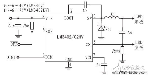
Figure 1: Typical application circuit diagram of LM3402
The logic of DIM1 is direct, so when the DIM1 port is high, the LM3402 will output a stable current; when DIM1 is low, any current output is prohibited. Therefore, the PWM signal is input to the DIM1 port of the LM340 2 to dim the LED array. The maximum logic low level of the PWM signal should be 0.8 V and the minimum logic high level should be 2.2 V. Leave the DIM1 port floating or connected to a logic high level. Once the input reaches 6 V, the LM3402 starts to operate.
Ground the OFF port to put the LM3402 into a low-power shutdown state (typically 90μA). During normal operation, the port should always be left open.
P89LPC932 is a low-power single-chip microprocessor produced by Philips. The power supply voltage is 3.3 V. It can operate with low power consumption and is suitable for many occasions that require high integration and low cost. Can meet various performance requirements. P89LPC932 uses a high-performance processor structure, and the instruction execution time only needs 2 to 4 clock cycles, which is 6 times that of the standard 80C51 device. P89LPC932 integrates many system-level functions, which can greatly reduce the number of components, circuit board area and system cost. There are 2 timers inside, which can be used as a PWM generator with 256 timer clock cycles. The electrical schematic of the LED dimming circuit is shown in Figure 2.
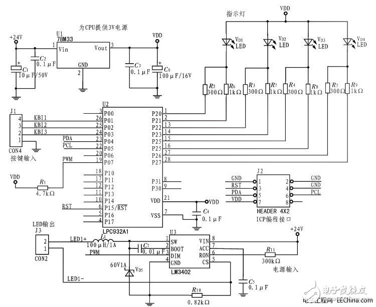
Figure 2: Electrical schematic of LED dimming circuit
144 Port Fiber Patch Panel is not only does it provide physical security for sensitive network connections, it also promotes better organization.144 Fiber Patch Panel can suit for FC Adapter , ST Adapter , SC Adapter , LC Adapter etc,Suitable for ribbon and bunchy fiber cable.144 port fiber optic patch panel Components have Cover, inner components, fiber connecting protector Inner components.And inner components have Bracket,Fiber Optic Splice Tray,Fixing Device .The 144 Fiber Patch Panel Environmental temperature is -25 - 55°C.
144 Port Fiber Patch Panel
144 Port Fiber Patch Panel,144 Fiber Patch Panel,Fiber Optic Patch Panel 144 Port
Foclink Co., Ltd , https://www.scfiberpigtail.com