Linear regulators have long been widely adopted in the industry. Linear regulators were once the foundation of the power industry before switch-mode power became mainstream after the 1960s. Even today, linear regulators are still widely used in many applications. Let's take a look at the basics of linear regulators.
First, the basic concept of linear regulator
A linear regulator uses a transistor or FET that operates in its linear region to subtract excess voltage from the applied input voltage to produce a regulated output voltage. All products are available in a small package with outstanding performance, and offer value-added features such as thermal overload protection and safety current limiting. The shutdown mode also reduces power consumption.
Second, the working principle of linear regulator
Let's start with a simple example. In an embedded system, a 12V bus voltage rail is available from the front-end power supply. On the system board, a 3.3V supply is required to power an op amp (op amp). The easiest way to generate a 3.3V voltage is to use a resistor divider from the 12V bus, as shown in Figure 1. Is this effective? The answer is often "no". The op amp's VCC pin current may vary under different operating conditions. If a fixed resistor divider is used, the IC VCC voltage will vary with the load. In addition, the 12V bus input may not be well regulated. In the same system, there may be many other loads sharing the 12V rail. Due to bus impedance, the 12V bus voltage will change as the bus load conditions change. Therefore, the resistor divider does not provide a regulated 3.3V regulated voltage for the op amp to ensure proper operation. Thus, a dedicated voltage regulation loop is required. As shown in Figure 2, the feedback loop must adjust the resistance of the top resistor R1 to dynamically adjust 3.3V on VCC.
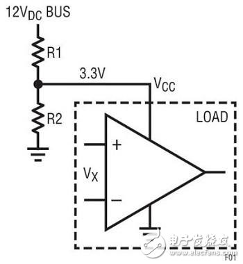
Figure 1 resistor divider uses a 12V bus input to generate 3.3VDC
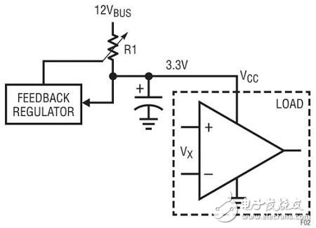
Figure 2 feedback loop adjusts the resistance of series resistor R1 to regulate 3.3V
Such a variable resistor can be implemented with a linear regulator, as shown in Figure 3. Linear regulators operate a bipolar or field effect power transistor (FET) in its linear mode. Thus, the transistor functions as a variable resistor in series with the output load. Conceptually, to construct a feedback loop, an error amplifier can be used to detect the DC output voltage using a sampling resistor network (RA and RB) and then compare the feedback voltage VFB to a reference voltage VREF. The error amplifier output voltage drives the base of the series power transistor through a current amplifier. When the input VBUS voltage drops or the load current increases, the VCC output voltage drops. The feedback voltage VFB will also drop. Therefore, the feedback error amplifier and current amplifier generate more current and are input to the base of transistor Q1. This will reduce the voltage drop VCE, thus restoring the VCC output voltage, thus VFB = VREF. On the other hand, if the VCC output voltage rises, the negative feedback circuit takes a similar approach to increase the VCE to ensure accurate regulation of the 3.3V output. . In summary, any change in VO is attenuated by the VCE voltage of the linear regulator transistor. Therefore, the output voltage VCC is always constant and in a good regulation state.
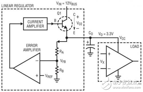
Figure 3 linear regulator can implement a variable resistor to regulate the output voltage
Dog Training Transmitter,Vibration Training Collar,Remote Control Vibration Collar,Rechargeable Dog Shock Collar
Elite-tek Electronics Ltd , https://www.aetertek.ca