1 Introduction Automotive air conditioning is the control center for the small temperature environment inside the car. Its role is self-evident. Because the past automotive air conditioning detection system is not necessary to use the integrated detection platform because of the monotonous control strategy, even if there is control process detection, most of the expensive acquisition devices such as data acquisition cards are used, and the communication method is mainly based on serial port communication. Access to the vehicle environment for monitoring [1]. In view of this situation, the detection system designed and developed in this paper mainly analyzes and analyzes the four engineering physical quantities in the operation process of electric vehicle air conditioner: the voltage and current of the fan, the high pressure and low pressure of the compressor port. This topic is derived from the design of the detection system required in the development process of a car air-conditioning system. It is mainly used to make the implementation of the control strategy of the air-conditioning system more transparent and intuitive, and provide a digital basis for the optimization of the control strategy; Development provides a reliable guarantee.
2 acquisition system design
2.1 overall design
This article refers to the address: http://
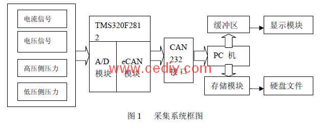
As shown in Figure 1, in the system, the software design of the DSP part mainly completes the following tasks: data acquisition cycle setting, AD conversion, data correction and filtering. And it can receive the acquisition start command sent by the host computer through the CAN bus to open the acquisition or close the acquisition function. After the acquisition starts, the four signals are sampled and software corrected according to the requirements. After the calibration is completed, the collection result is saved in the CAN mailbox. The CAN control module transmits. In this system, voltage and current are collected.
2.2 Hardware Part The TI company's TMS320F2812 is the core of the four-channel data acquisition system. This DSP chip is a member of TI's 2000 series, with a maximum frequency of 150MHz and powerful digital signal processing capability [2]. The on-chip 12-bit AD converter has 16 channels with a conversion rate of 12.5MSPS (the ADC clock is 25MHz), which meets the design requirements of the system in terms of acquisition speed and accuracy. Moreover, the AD module can be triggered in a variety of ways to meet different mission needs. The analog signal input to the 2812 AD terminal is obtained by sensor acquisition and transformation. The sensor output signal used in this system is a current loop signal of 4-20 mA, and the AD analog input range is a 0~3V voltage signal.
CAN is the abbreviation of Controller Area Network (Control Area Network). It was first introduced by BOSCH of Germany and used for data communication between internal measurement and execution components of automobiles. Its bus specification has been developed into an international standard by ISO international standards [ 3]. It is widely used in automotive electronics and industrial control. Its signal transmission medium is ordinary twisted pair, and the communication speed is up to 1Mbps. The CAN bus has strong anti-interference ability. The system adopts the CAN bus communication mode, which also facilitates the access of the whole vehicle debugging.
2.3 software part design
2.3.1 DSP Software Section
This part of the software mainly consists of two parts: AD conversion of analog signals and CAN bus communication. Because the TMS320F2812 has a built-in 12-bit AD converter, the conversion part can be divided into AD module configuration and data conversion processing; while the AD module configuration mainly includes work and channel selection. In this system, the continuous conversion mode is selected; the analog quantity to be collected is four, and the A and B channels are each configured with two correction input ports, so a total of eight analog input ports are required.
The 50ms200ms set period is, the high and low voltage sampling periods are. Some configuration procedures are as follows: ...
AdcRegs.ADCTRL1.bit.SEQ_CASC = 0; //Double sorting occurs
AdcRegs.ADCTRL1.bit.CONT_RUN = 1; //Continuous conversion mode
AdcRegs.ADCTRL1.bit.CPS = 0; //The division factor is 1
AdcRegs.ADCMAXCONV.all = 0x0055; // There are 12 conversions, the sample value is taken 2 times, and the standard value is 1 time.
AdcRegs.ADCCHSELSEQ1.all = 0x1100; / / conversion sequence CAN bus communication mainly includes the definition of eCAN module mailbox in TMS320F2812 and the setting of mailbox interrupt subroutine [6].
Some configuration procedures are as follows:
ECanaMboxes.MBOX0.MSGID.all = 0x003FFFFF; // mail0:00F
ECanaMboxes.MBOX5.MSGID.all = 0x0FFFFFFF; // mail5:3FF
// Configure Mailboxes 0-3 as Tx, 4,5 as Rx
ECanaRegs.CANMD.all = 0x00000030; // Enable Mailboxes
ECanaRegs.CANME.all = 0x0000003F; // Specify that 2 bits will be sent
The CAN module has two types of interrupts, one is a mailbox-related interrupt, and the other is a system interrupt, which is used to handle errors or system-related interrupt sources [4]. In this system, communication between CAN and host computer is mainly realized by mailbox interrupt.
The interrupt procedure of CAN mailbox is as follows:
Interrupt void can_send(void)
{
If((((int) ECanaRegs.CANGIF1.all)<0) && (ECanaRegs.CANGIF1.bit.MIV1==4))
{ IER |=M_INT1;} if(((int) ECanaRegs.CANGIF1.all)<0) && (ECanaRegs.CANGIF1.bit.MIV1==5)) { IER = M_INT9;} PieCtrlRegs.PIEACK.bit.ACK9 = 0x1;
}
Taking high voltage as an example to illustrate the corresponding tasks of the system in data acquisition, data conversion and transmission.
Pre_High= AdcRegs.ADCRESULT6 >> 4 + AdcRegs.ADCRESULT7 >> 4; Pre_High = Pre_High << 1; //High voltage value Pre_High = Ave_cur * CalGain - CalOffset *CalGain; ECanaMboxes.MBOX2.MDL.word.LOW_WORD = Pre_High; ECanaRegs.CANTRS.all=0x0000000C;
While(ECanaRegs.CANTA.all!=0x0000000C){} ECanaRegs.CANTA.all=0x0000000C;
The actual operation proves that the execution result meets the design requirements, indicating that the part of the program design fully meets the expected task scheduling plan, and can work well with the hardware platform.
2.3.2 PC software part This part of the software uses object-oriented programming technology, the hardware operation function of CAN232 interface card has been packaged in ControlCAN.dll, add ControlCAN.lib and ControlCAN.h in Visual C++ project Files and header files. Convenient to call in the program. Set the corresponding parameters of CAN232 in the compiled application.
Start the acquisition process. Each time the collected data is written to the data file and sent to the data buffer to realize data sharing between the acquisition module and the display module. The flow chart of this part is shown in Figure 2:

In this project, you can use VC's own property page dialog box and set the corresponding four property pages to easily switch and observe the collected data waveforms, data statistics, data frames, and statistics of collected events. The display module uses the measurement control (CNiGraph) of Measurement Studio. Measurement Studio is a tool developed by National Instruments for testing and control, seamlessly integrating powerful data acquisition and analysis into the Visual Studio environment. Measurement Studio provides users with intuitive measurement hardware interfaces, advanced analysis functions, scientific user interface controls, and measurement data networks to greatly improve the development efficiency of data acquisition and analysis systems [5].
In this system. The amount of data is huge, and for this situation, an Access database file is created. Access is a typical relational database suitable for ordinary occasions. According to the design principle of relational database and the requirements of this paper, the operation of the database is transformed into the operation of the corresponding recordset, and the implementation language is implemented by SQL language. 3 is a waveform diagram of four-way data of an air-conditioning compressor. FIG. 4 is a statistical diagram of data values ​​corresponding to four-way data.
3 Conclusion This acquisition system has been tested several times by hardware and software, which proves that it can meet the collection of relevant parameters of automotive air-conditioning compressor system. The designed upper computer system can cooperate with the collection node to realize data display, storage, data recording, Retrieval and other functions, using multi-threading, critical mass and other programming techniques, combined with Measurement Studio user interface controls and analysis function library, facilitates and quickly implements the data acquisition system in Visual C++ environment, effectively reducing the complexity of such program development. Sexuality shortens the cycle of program development. The experiment proves that the system has the advantages of real-time and scalability. The author of this paper innovates: Combining DSP and CAN bus technology into the online detection system, the anti-interference ability, reliability and accuracy of the system are guaranteed; the calculation speed and work efficiency are improved.
Zhejiang Synmot Electrical Technology Co., Ltd , https://www.synmot-electrical.com