With the rapid development of electronics and sensing technology, temperature measurement and control have been widely used in civil, industrial and aerospace technologies. Small, low-power, low-cost, high-reliability temperature sensors have attracted widespread attention. In the field of actual production and life, temperature is an indispensable part of environmental factors, and timely and precise control and detection of temperature is particularly important. Based on AT89S51 single-chip microcomputer and LM35 temperature sensor, this paper designs a temperature acquisition and display system with high sensitivity, strong anti-interference ability and stable and reliable operation.
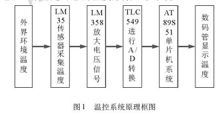
1, system structure and working principleThe temperature acquisition display system circuit is composed of a temperature acquisition module, an A/D conversion module, a single chip control module, a digital tube display module and a download module. The working principle of the circuit is: firstly, the temperature of the external environment is collected by the LM35 temperature sensor, amplified by the LM358 10 times and input to the A/D sampling circuit as a voltage, and the digital value of the temperature is transmitted to the single chip system by the A/D converter TLC549. Then, the MCU system drives the digital tube to display the temperature. The temperature measurement range of the LM35-based single-chip temperature acquisition display system designed in this paper is 25 ° C ~ 80 ° C temperature acquisition display system circuit is an open loop control system system block diagram shown in Figure 1:
The system core hardware circuit design mainly includes the design of the temperature acquisition module, the design of the A/D conversion module, the design of the single-chip control module, the design of the digital tube display module and the design of the download module.
2.1, the design of the acquisition module
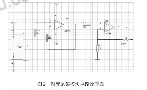
The sensor is the first link of signal input and one of the key aspects of the performance of the whole test system. Therefore, the correct selection of the sensor is particularly important. In this system, the core hardware of the temperature acquisition module uses LM35 temperature sensor, which has high working precision and wide linear working range. Its output voltage is linearly proportional to Celsius temperature, and the voltage rises every 1 °C rise in temperature. 10ms. The LM35 provides external room temperature accuracy of ± 1 /4 ° C without external calibration. Considering many aspects such as economical application, the system uses LM35 temperature sensor and LM358 amplifier circuit to design the temperature acquisition module. The design schematic diagram is shown in Figure 2. In Figure 2, the weak voltage collected by the LM35 sensor is amplified 10 times by the LM358 amplifier circuit and sent to the microcontroller.
2.2, /D conversion module design
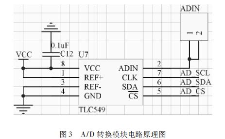
The core hardware of the A/D conversion module uses TLC549, which is a CMOS serial 8-bit A/D converter. The integrated circuit has an 8-bit switched capacitor successive approximation ADC. The A/D chip conversion time is 17us, and the voltage is supported. It is 3V to 6V. The TLC549 uses only the input/output clock, and the input is input with the control of the chip select (CS). The TLC549's input/output clock has an input frequency of up to 1.1MHz. The design schematic of the A/D conversion module is shown in Figure 3:
2, 3 MCU control module design
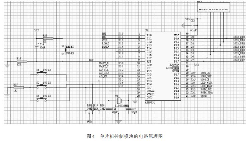
Because the 8031 ​​chip does not have program memory internally, it needs to be externally expanded, which not only takes up a lot of space, but also increases the complexity of the circuit. Based on a simplified embedded control system architecture, the 51 series microprocessors should be widely used in personal PCs, automation, and even military applications. The core hardware of the MCU control module uses AT89S51, which is a low-power, high-performance CMOS 8-bit microcontroller with 8K system programmable flash memory, readable and writable. With online programming capabilities, the software can be debugged online to match the hardware. The system drives the digital tube through the single-chip microcomputer to display the measured temperature. The design schematic diagram of the MCU control module is shown in Figure 4.
2.4, the design of the digital tube display module
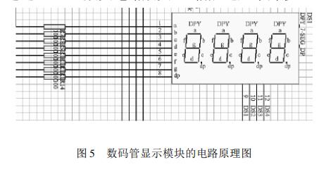
The display system is an important part of the single-chip control system, which is mainly used to display the values ​​of various parameters, so that the staff can grasp the production process in time. The digital tube display module uses the ordinary 8 as the digital tube, and uses the single-chip microcomputer to drive the digital tube to display the measured temperature. The schematic diagram of the digital tube display module is shown in Figure 5:
2.5, the design of the download module
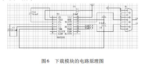
The download module can realize single-machine communication, multi-machine communication between the single-chip microcomputer, and communication with the computer. The system mainly realizes downloading the program from the computer to the single-chip microcomputer, thereby driving the whole circuit board work. The core hardware of the download module uses the serial port MAX232 and RS232. The MAX232 is a chip that converts TTL and RS232 levels. The microcontroller passes the internal universal asynchronous receiver/transmitter
(UART) Communicates with the MAX232. Download the design schematic of the module, as shown in Figure 6.
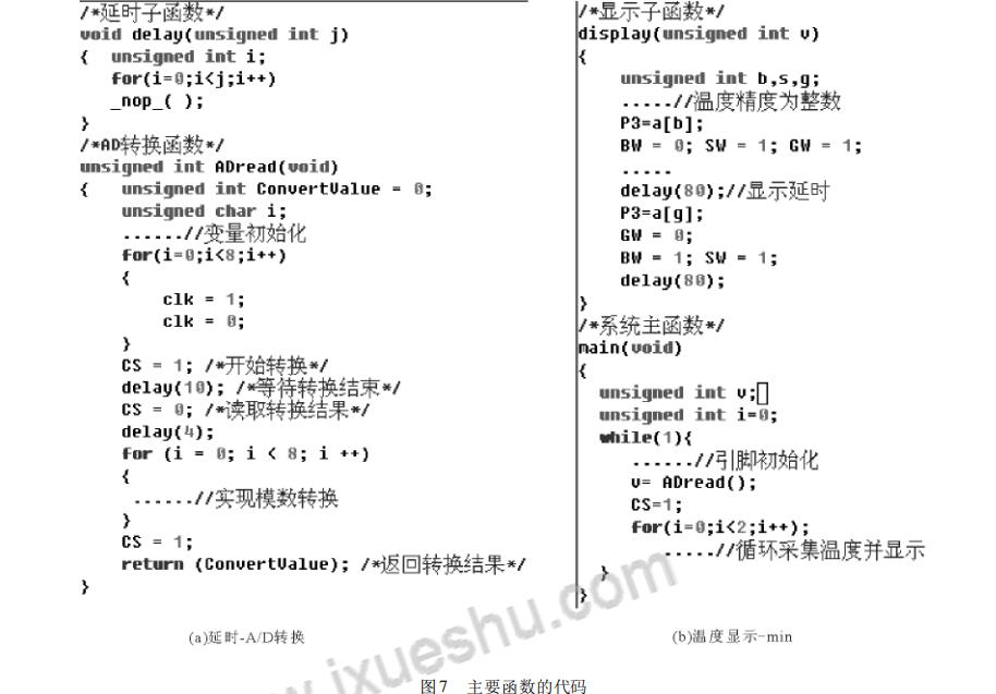
The system software design adopts C language programming and modular structure for development. The program mainly includes main function, delay sub-function, A/D conversion sub-function and temperature display sub-function. Among them, the delay subfunction and the A/D conversion subfunction are shown in Fig. 7-a, and the temperature display subfunction and system main function are shown in Fig. 7-b.
Performance tests show that the constant temperature movement in the room, the room temperature changes are not obvious. Similarly, the temperature is collected outdoors, and the changes are not obvious. When using a finger to hold the chip or use a heater or heater to heat the chamber. The temperature changes rapidly and the temperature rises sharply. Test results show that the system has short response time and high sensitivity.
5 ConclusionTemperature acquisition and control systems are widely used in modern life. The system realizes the temperature collection and display function. After repeated tests, the system has the characteristics of short response time, strong anti-interference ability, stable and reliable operation, and has the advantages of small size and low cost, and has high engineering value. It has broad application prospects in daily life and academic research. The temperature range of this system is between 25 °C and 80 °C, and the accuracy of the temperature value is an integer. The next step is to study how to use frequency detection control technology to further improve the accuracy and range of temperature measurement. At the same time, it can be used for multi-function products such as temperature measurement, temperature warning and control.

AC wall 5V 2A power adapter with multiple tips works for many small 5V electronics. Like Scanner, Router, Bluetooth speaker, Foscam Wireless IP Camera, CCTV camera, USB hub, bluetooth GPS Receiver, tv box, tablets, Baby Monitor, Graco Swing, Home Phone System, VoIP Telephone Routers, Serato DJ Controller, DVR, ADSL Cat, External battery, hubs, switches, Led Strip, String Lights, vibrator, Raspberry pi 3 Raspberry Pi A/A+/B/B+ Raspberry Pi Zero and more 5V devices. (5V ONLY)
Worldwide Input: 110-240V; Output: 5V 1000mA, 1.5A, 1.75A, 5V 1A, 5V 500mA, 5V 2.1A, Max 10W. DC Tip Polarity: Central Positive(+). Please read manual carefully before using 5vdc power supply.
Design-safeguard features against incorrect voltage, short circuit, internal overheating and overloading. This 5v Ac power supply charger is made from quality material to ensure the long lifetime. Power your 5v electronics perfectly and replaces lots of 5 volt power chargers
Package include: 1 x High Quality 5V 2A AC DC Power Adapter, 1 Set x Tips
5V Switching wall charger 6V Switching wall charger 9V Switching wall charger 12V Switching wall charger 15V Switching wall charger 19V Switching wall charger 24V Switching wall charger 36V Switching wall charger 48V Switching wall charger
Shenzhen Waweis Technology Co., Ltd. , https://www.waweisasdapter.com