Programmable Logic Controller is a digital computing operation electronic system specially designed for application in industrial environments. It uses a programmable memory that stores instructions for performing operations such as logic operations, sequence control, timing, counting, and arithmetic operations, and controls various types of mechanical equipment or production through digital or analog input and output. process.
Basic structure of PLCThe programmable logic controller is essentially a computer dedicated to industrial control. Its hardware structure is basically the same as that of a microcomputer. The basic composition is shown in the following figure. The basic structure is described in detail as follows:
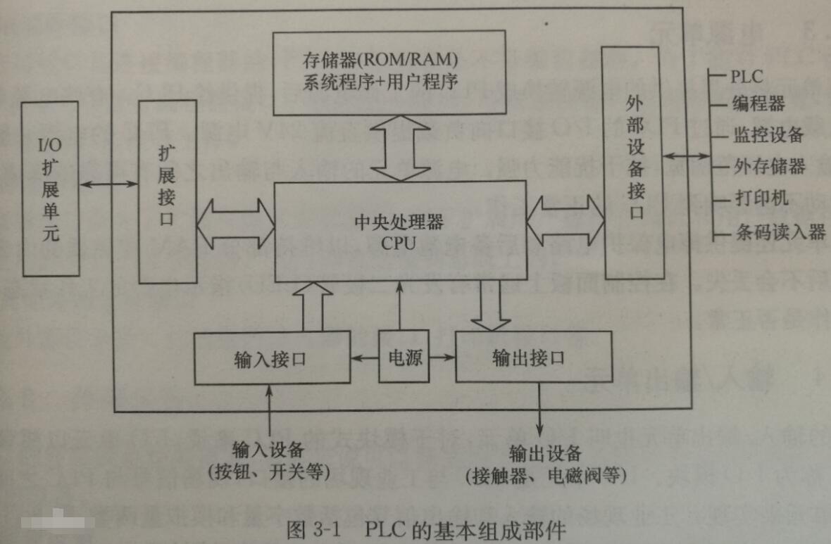
The power supply is used to convert the AC power into the DC power required inside the PLC. At present, most PLCs use a switching regulator power supply.
Central processing unit (CPU)
The central processing unit is the control center of the PLC and the core component of the PLC. Its performance determines the performance of the PLC.
The central processing unit is composed of a controller, an arithmetic unit and a register. These circuits are concentrated on one chip and connected to the input/output interface circuit of the memory through an address bus and a control bus. The role of the central processor is to process and run user programs, perform logical and mathematical operations, and control the entire system to coordinate.
Memory
Memory is a semiconductor circuit with memory function that stores system programs, user programs, logic variables, and other information. The system program is a program that controls the PLC to implement various functions, is written by the PLC manufacturer, and is solidified into a read-only memory (ROM), which the user cannot access.
Input unit
The input unit is an input interface between the PLC and the controlled device. It is a bridge for the signal to enter the PLC. Its function is to receive the signal from the main component and the detection component. The input types are DC input, AC input, AC and DC input.
Output unit
The output unit is also a connection component between the PLC and the controlled device, and its function is to transmit the output signal of the PLC to the controlled device, that is, convert the weak electric signal sent by the central processor into a level signal, and drive the actuator of the controlled device. . The types of outputs are relay output, transistor output, and gate output.
In addition to the above parts, PLC has a variety of external devices depending on the model. Its function is to help programming, monitor and network communication. Commonly used external devices are programmers, printers, cassette tape recorders, computers, and the like.
How does PLC work?When the PLC is put into operation, its working process is generally divided into three stages, namely, input sampling, user program execution and output refresh. Completing the above three phases is called a scan cycle. During the entire operation, the CPU of the PLC repeatedly executes the above three stages at a certain scanning speed.
(1) Input sampling stage
During the input sampling phase, the PLC reads all input states and data in a scan mode and stores them in the corresponding cells in the I/O map area. After the input sampling is finished, it is transferred to the user program execution and output refresh phase. In these two phases, the status and data of the corresponding unit in the I/O map area does not change even if the input status and data change. Therefore, if the input is a pulse signal, the width of the pulse signal must be greater than one scan period to ensure that the input can be read in any case.
(2) User program execution stage
During the user program execution phase, the PLC always scans the user program (ladder) in order from top to bottom. When scanning each ladder diagram, the control lines formed by the contacts on the left side of the ladder diagram are always scanned first, and the control lines composed of the contacts are logically operated in the order of first left, then right, first up and then down. And then refreshing the state of the corresponding bit of the logic coil in the system RAM storage area according to the result of the logic operation; or refreshing the state of the corresponding bit of the output coil in the I/O map area; or determining whether to execute the ladder diagram The specified special function instructions.
That is, during the execution of the user program, only the status and data of the input point in the I/O map area will not change, and the status of other output points and soft devices in the I/O map area or the system RAM storage area. And the data may change, and the ladder diagrams listed above, the program execution results will work on the ladder diagrams that use these coils or data below; on the contrary, the ladder diagrams below are The state or data of the refreshed logic coil can only go to the next scan cycle to work on the program that is listed above.
(3) Output refresh phase
When the scanning user program ends, the PLC enters the output refresh phase. During this time, the CPU refreshes all the output latch circuits according to the corresponding state and data in the I/O map area, and drives the corresponding peripherals through the output circuit. At this time, it is the real output of the PLC.
The same several ladder diagrams are arranged in different order and the results are different. In addition, the results of the operation of the scanning user program are different from the results of the parallel operation of the hard logic of the relay control device. Of course, if the time taken by the scan cycle is negligible for the entire run, there is no difference between the two.
In general, the scan cycle of the PLC includes self-diagnosis, communication, etc., that is, one scan cycle is equal to the sum of all the times such as self-diagnosis, communication, input sampling, user program execution, and output refresh.
PLC is a programmable controller. Its control circuit diagram is mainly its internal ladder diagram except electrical wiring diagram. Ladder diagrams are not much different from general electrical control circuit diagrams. That is, "the coil is energized, the contact changes state; the coil loses power, and the contact returns to its original shape."
Looking at the circuit diagram with PLC, you should first know the meaning of the graphics in the ladder diagram (such as what the symbol of the coil and contact is used, what its function is, etc.) and then understand the meaning of its text symbol. Finally, pay attention to the connection of its input/output channels.
It is the same as the ordinary circuit diagram, it has a normally open, and it has a normally closed.
Simple input and output can be seen like this:
X terminal is input
Y terminal is the output
Think of PLC as an integrated big appliance
More complex points are A/D, D/A, and pulses. General equipment has its supporting reference book, take a closer look.
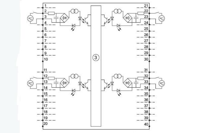
This is the wiring diagram of the PLC's digital input (DI) module. The large box shows the internal circuit board wiring. The large box shows the DI signal wiring diagram. The terminal number is represented by numbers. There are 16 DI signal channels. For example, channel 2-3: externally connect a switch and an electric source (the symbol indicates DC or AC power), form a loop with the internal circuit, and the DC/AC power supply passes through the current limiting resistor and the rectifier bridge to form an internal DC power supply. The flow coil operates on the photoelectric coupling switch and the light emitting diode. The signal of the photoelectric coupling switch is transmitted to the internal portion, and the LED is used as a status light to recognize whether the external circuit of the channel 2-3 is turned on. Other channels are related to this.
The PLC does not need a circuit diagram. See if you want to implement the magic function and write the appropriate ladder diagram. The PLC is customized according to the needs, and will be equipped with a wiring diagram at random! Its wiring diagram must be very detailed, just follow the wiring.
How to understand the plc ladder diagramLadder diagram is the most used graphical programming language for PLCs and is called the first programming language of PLC. The ladder diagram is similar to the circuit diagram of the electrical control system. It has the advantages of being intuitive and easy to understand. It is easy to be mastered by the factory electrical personnel, and is especially suitable for switching logic control. Ladder diagrams are often referred to as circuits or programs, and ladder diagrams are called programming. Ladder programming read: from left to right, top to bottom.
1. Soft relay
Some programming elements in the PLC ladder diagram follow the name of the relay, such as input relays, output relays, internal auxiliary relays, etc., but they are not real physical relays, but some storage units (soft relays), each soft relay Corresponds to a memory location of the image register in the PLC memory. If the storage unit is in the "1" state, it means that the coil of the corresponding soft relay in the ladder diagram is "energized", the normally open contact is closed, and the normally closed contact is open, and the state is called "1" of the soft relay. " or "ON" status. If the memory cell is in the "0" state, the state of the coil and the contact corresponding to the soft relay is opposite to that described above, and the soft relay is said to be in a "0" or "OFF" state. These "soft relays" are often referred to as programming elements in use.
2. Energy flow
When the contacts are turned on, there is an imaginary "concept current" or "energy flow" that flows from left to right, which is consistent with the order of logic operations when executing the user program. Energy flow can only flow from left to right. Using the concept of energy flow can help us better understand and analyze ladder diagrams.
3. Busbar
The vertical common lines on either side of the ladder diagram are called bus bars. When analyzing the logic relationship of the ladder diagram, in order to borrow the analysis method of the relay circuit diagram, it can be imagined that there is a left-right and a negative DC power supply voltage between the left and right busbars (left and right busbars), and there is "power flow between the busbars". "Flow from left to right. The right busbar can be drawn.
4. Logic solution of ladder diagram
According to the state and logical relationship of each contact in the ladder diagram, the state of the programming element corresponding to each coil in the figure is obtained, which is called the logic solution of the ladder diagram. The logic solution in the ladder diagram is performed from left to right and top to bottom. The result of the solution can be used immediately by the subsequent logic solution. The logic solution is based on the value in the input image register, not on the state of the instantaneous external input contact.
-||-Look at the normally open switch
-|/|- is seen as the output of the switch in the normally closed brackets
5.PLC ladder reading steps
Step 1: You need to understand that your PLC-controlled equipment has actions that require operational control, operational status, and protective actions.
The second step: first from the input end of the PLC, to understand the meaning of the input switch command at each point of the input, which is the start, which is the stop „
The third step: starting from the output of the PLC, the output signal of each point of the output and the meaning of executing the switch electrical appliance are understood, which action is activated and which action is stopped.
Step 4: Open the ladder diagram, analyze the logical relationship between input and output of one step and one step, and control, execute and complete the operation tasks respectively.
Step 5: Repeat one, two, three, and four steps until you are familiar with and thoroughly understand the control logic principle of the overall PLC ladder diagram and the working principle of the equipment.
The company adheres to the management policy of "seeking truth and dedication" and a strict quality assurance system. In the new century, we will follow the tenet of "innovation, progress and rigor" and a forge ahead enterprise with "excellent quality and excellence". Spirit, the supreme product, add wings to your enterprise take off. Carefully do a good job of each product, the highest quality, and integrate a dedicated attitude, dedicated spirit, skilled practice, and good reputation into the details of the service.
High Voltage Connector,High Voltage Terminal Wire Connectors,High Voltage Terminal Connectors,High Voltage Terminal Connector Terminal
Sichuan Xinlian electronic science and technology Company , https://www.sztmlchs.com