With the development of social and economic life on the demand for railway transportation and the continuous development of science and technology, the capacity of railway transportation is increasing day by day, and the requirements for railway transportation security are even higher. However, with the implementation of the five speed-ups on the road, the safety hazards at crossings have become more and more prominent and have become the bottleneck of railway transportation safety and railway transportation capabilities. Crossing monitoring alarm devices have a very positive significance in reducing the crossing accident rate and protecting the safety of crossings. However, from the current research results and practical applications, most of the track circuit type, mechanical type, and a small number of Doppler radar and sound receiving type. Each has its own advantages and disadvantages in terms of performance, and it is also different in cost and size.
In this paper, a magneto-resistive sensor is used. According to the effect of magnetic field, an alarm information collection device for train track is designed, and the design method of hardware and software is given.
2 system working principleThe phenomenon that the resistance value of the energized conductor changes in the magnetic field is called the magnetoresistance effect. For iron, cobalt, nickel and their alloys, if these metals are made into thin-film strip conductors, their resistance changes when a current passes through them. The magnitude of the change is due to the combination of the magnetization direction and current flow of the two magnetic fields inside and outside. The relationship varies and tends to increase in the same direction; otherwise decreases [1]. As shown in Figure 1, the four permalloys constitute a Wheatstone bridge, and the change in the resistance value converts the applied magnetic induction to a differential voltage output [2].
Large ferromagnetic objects, such as trains, can be seen as models consisting of multiple north and south magnets. When the train passes by, it will cause the disturbance of the earth's magnetic field, and its comprehensive effect is to cause distortion and distortion of the magnetic field lines of the earth's magnetic field. When the sensor is in the changing magnetic field, it can be known from the magnetoresistance effect that a differential voltage will be generated at the differential output of the sensor, which is the theoretical basis for the system to detect the train.
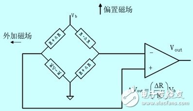
Figure 1 Magnetoresistive sensor schematic
3 system hardware designThe hardware part of the train track alarm information collection system is mainly composed of a data acquisition module and a data processing module. The data acquisition module is responsible for the collection of magnetic field signals. Its main core is the magnetoresistive sensor. When the train approaches the magnetoresistive sensor, the sensor will collect the magnetic field change signal, through signal amplification and a/d conversion, and convert it into a discrete digital signal and send it to the microcontroller (microcontroller). The main component of the data processing module is a single-chip microcomputer. SCM is responsible for the timing control of each chip, and in order to improve the system's anti-jamming capability, it is necessary to filter the collected data before it can be sent to the serial port, which is read by the communication device. The hardware design diagram of this system is shown in Figure 2.
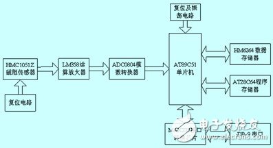
Figure 2 system hardware design diagram
3.1 Data Acquisition Module
In this system, the magnetoresistive sensor used was a hmc1051z single-axis magnetoresistive sensor manufactured by Honeywell. The hmc1051z has a wide range of angles, with a resolution of 0.07° and a sensitivity of 1.0 mV/v/gauss at ±45°, and a full-scale output of 120mv at 5V. No internal moving parts, low intrinsic impedance, strong immunity to electromagnetic noise and interference, and built-in set/reset band, can reduce temperature drift, nonlinearity error, and influence on the output signal in a high magnetic field environment. The on-chip bias circuit eliminates the effects of magnetic field distortion [3].
The lm358 op amp with two 4.99kω, two 1.00mω resistors and a 150pf capacitor form an amplifying circuit with a low-pass filter with a gain of 200 and a bandwidth of approximately 1khz, enabling amplification of the sensor output signal and hardware Filtering.
The a/d converter uses an adc0804 analog-to-digital converter with an 8-bit resolution to perform analog-to-digital conversion on the amplified signal.
3.2 Data Processing Module
Atmel's at89c51 microcontroller and mcs-51's instruction system and pins are compatible, and comes with 4kb e2rom. But for future upgrades and feature extensions, the at89c51 memory has been expanded here. The program memory at28c64 and the data memory hm6264lp-70 are all 8kb in size, and p0.0-p0.7 and p2.0-p2.4 provide 13-bit addresses, and 74ls373 latches the lower 8-bit address. Use p2.5 and p2.6 to wire these two memories.
Due to the need to send signals to the db-9 serial port connector, max232 is used here to convert between ttl and rs-232 levels. Connect the t1in pin of max232 to the serial transmit pin txd of at89c51, r1out to the serial receive pin rxd of at89c51; Corresponding r1in, t1out to the 9-pin serial port connector (db-9) Corresponding rxd (2) No.) and txd (No. 3).
4 System Software DesignThe software design part of this system is mainly the design of the a/d conversion subroutine and the data processing subroutine, and is developed using keil μvision2 development tools.
4.1 a/d conversion subroutine
The a/d conversion subroutine flow chart is shown as in Fig. 3. First make (this design end has been grounded) is low, start adc0804, after querying interrupt 0, 100μs after the rising edge of the analog-to-digital conversion is complete, and the result is stored in the data latch, the data is in the low level The signal is sent to port p1.
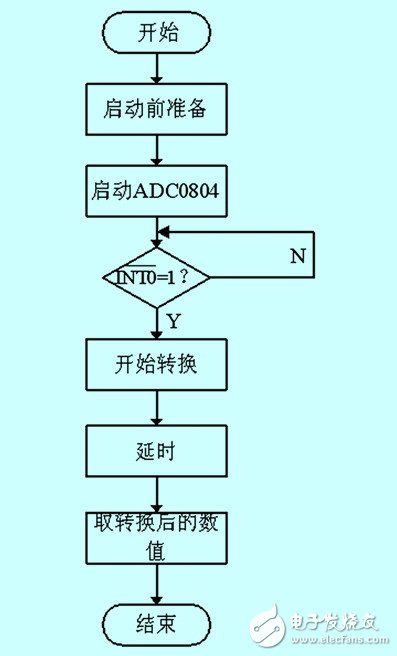
Figure 3 a/d conversion subroutine flow chart
4.2 Data Processing Subroutines
The data processing subroutine of this system is to perform anti-jamming processing on the collected data to improve the stability and reliability of the system. The flow chart is shown in Figure 4.
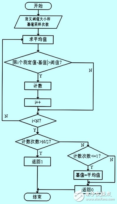
Figure 4 data processing subroutine flow chart
The data processing subroutine uses a constant threshold and a dynamic base value algorithm to achieve the system's anti-jamming capability, that is, the most recent collected data and the base value are subtracted, and the subtracted value is judged. If the value is greater than the threshold, the record is recorded. At a certain number of times, it can be assumed that the train has arrived at this time; the size of the base value can be updated in real time based on changes in the surrounding magnetic field. The program written according to this algorithm can achieve the purpose of system self-adaptation on the one hand, and can also freely set the level of anti-jamming processing (threshold size and base value sampling times) on the other hand to facilitate different kinds of needs.
5 Concluding remarksTaking the magnet and the radio as the target objects respectively, observe and record the voltage rms value of the differential output terminal of the magneto-resistive sensor and the voltage value after magmplification of the lm358 op amp 200 times under the operating conditions far and close to the system. The two groups of experiments were performed ten times respectively, and the angle and position of the target object cut in each time were different from each other when approaching the system. The experimental results are shown in Tables 1 and 2.
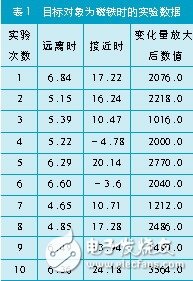
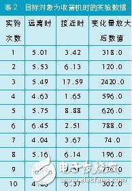
From the analysis of the experimental results, the magnetic field intensity of the object and the position of the object relative to the sensor will cause a large change in the measured value, and the change of the object with a large magnetic field intensity is obvious, and this characteristic can be used to judge the arrival of the train.
6 ConclusionThis article expounds the development process of train track alarm information collection system based on magnetoresistance effect from the perspective of engineering application. The system has the advantages of low power consumption, low cost and stable performance. The system can be connected with wireless devices such as gprs to form a remote alarm system, so it has a certain practical value.
Adapter Cable,Hdmi Converter,Av To Hdmi Converter,Wii Hdmi Adapter
Dongguan Tuojun Electronic Technology Co., Ltd , https://www.fibercablessupplier.com